

Minki I and Minki II
1992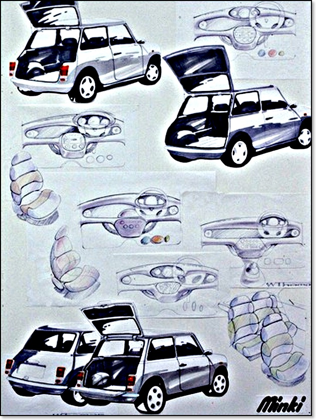
The thinking behind the replacement for the Mini started back in about 1992, while under the ownership of British Aerospace and called at that time The Rover Group.
So how was the name MINKI arrived at, simple, put a ‘K’ series engine into a Mini and you have MINKI.
At the time the general feeling was that because the design was then thirty three years old, technology had moved on so much, and with new legislation on emissions and crash testing etc., that it was best to start with a clean sheet.
The first part of the concept stage was to do an appraisal of the current Mini and see how improvements could be made.
1) Improve the powerunit, by installing the ‘K’ series engine with a 5-speed gearbox
2) Improve the suspension, by installing hydragas suspension.
3) Improve the driving position, by installing better seats, altering the rack of the steering column, and along with the fascia / controls
4) Improve its overall luggage capacity, by making it into a hatchback and altering the rear end package.
It must be remembered that some times projects are started on, even no formal programme budget has been agreed. This can actually work quite well as it means that on a ‘zero-cost’ bases by using scrapped components and with no design resource it gives the Project Manager and the skilled fitters the flexibility to change the design as the work progresses. This work would be carried out in the Flight Shed Chassis workshop, were a small team who were used to working this way “in the good old days”.
A decision was made that the work would be divided into three parallel activities:-
1) A running vehicle modified to take the hydragas suspension and ‘K’ series engine / 5-speed gearbox.
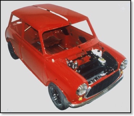
2) A scrap bodyshell modified at the rear end to demonstrate the improved rear package and hatchback.
3) Another scrap bodyshell to develop the driver environment, with a ‘clayed up’ fascia, revised steering column arrangement, etc.
The above information, along with a brochure and slide show were used to make a presentation to senior management in October 1992.
Running Vehicle
It was now time to look at making a running vehicle, so Tony Spillane used his previous chassis experience to collect together various drawings and slide them over each other to develop ideas for the running vehicle. This allowed the following modifications to be made:-
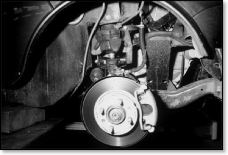
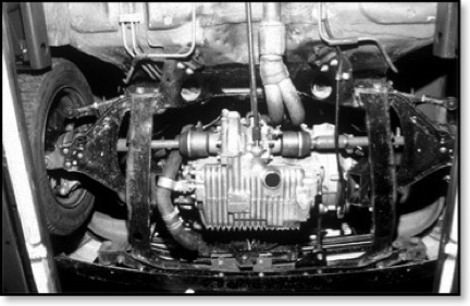
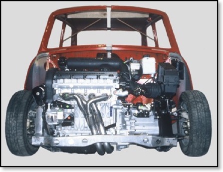
The hydragas suspension required the geometry of the Rover 100 front suspension, which in turn required the front subframe to hold it all together. This could be grafted into the Mini as long as it was narrowed across the car to get back to Mini front track, and the hydragas units were ‘split’, so that the gas egg was remote. This allowed the suspension tower of the Rover 100 front subframe to have a plate welded on, so that it could then bolt up to the Mini bodyshell using the standard Mini ‘big bolt’ that goes through the body cross beam into the subframe tower. The front cross beam of the Rover 100 subframe also had to be replaced to stop it appearing in fresh air in front of the Mini’s front bumper!
It was relatively easy, using prototype dismantlable hydragas units to fit the ‘displacer’ part in the subframe tower, and the ‘gas egg’ in the front wing, using the redundant damper top mounts. Finally, the modified front subframe was dangled into position, and ‘persuaded’ to fit by attention to the bulkhead, inner wings, etc, as well as shortening a Rover 100 steering rack to fit.
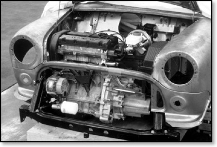
The big issue now was that the subframe was around four inches too narrow to take the ‘K’ series engine and gearbox. However, on the ‘K’ series engine each cylinder is around four inches, so the obvious thing was to make a three cylinder version! No problem, as a three cylinder engine cylinder head was available, from the KV6 engine. The crankcase was made by chopping down a four cylinder casting pattern to cast a three cylinder crankcase, that could then have each end machined as normal. This allowed us to complete the powertrain installation, and it all went in perfectly, with the five speed gearbox and front mounted radiator. The only thing we needed was a proper three cylinder crankshaft, with its 120 degree crankpin layout. Unfortunately, this was going to cost money.
Minki Suspension
We had proved the front end layout, but now wanted to drive the vehicle to develop the hydragas suspension.
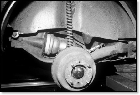
Rear Suspension
We had converted the standard Mini rear suspension and subframe to take a hydragas unit very easily. There was nothing for it but to re-install the good old ‘A’ series engine and underslung gearbox to get it all mobile. This meant new engine mounts to get back to the Rover 100 subframe. We did look at whether we could have used the Maestro ‘A’ series engine and end-on gearbox, but it was too tight – the ‘A’ four cylinder engine was roughly equivalent to a ‘K’ three and a half cylinder engine in length!
'A' Series Power Unit
Once the vehicle was running, it soon became apparent that the ride was awful! This was found to be due to the short connecting pipe from the displacer to the gas egg, that was too restrictive. A larger smoother flow pipe solved the problem.
Some ride development work was done, including the fitting of old hydrolastic rear helper springs to get the necessary preloads into the system. This was overseen by engineer Spike Hawthorn, who loved to create pages of mathematical formulae. However, some numbers would always drop out at the end, and when the suspension parameters were set up to Spike’s predictions, we got a tremendous vehicle ‘straight out of the box’! The vehicle exhibited a much better ride than standard, whilst retaining its ‘Mini-ness’ to drive, and was assessed by many Rover Group engineers, managers and directors.
The Rear Package
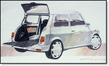
Some sketches soon showed that a traditional one-piece full length hatchback on a Mini didn’t look right, and got in the way when trying to load / unload the vehicle. A split tailgate, like the Austin A40 (and subsequently copied on the Range-Rover) suited much better. This was mocked up on a scrap bodyshell in the Tinsmiths department at Canley. Getting a suitable hinge arrangement for the upper section was difficult with the roof curvature and drain channel, as we didn’t want to change the roof panel or style.
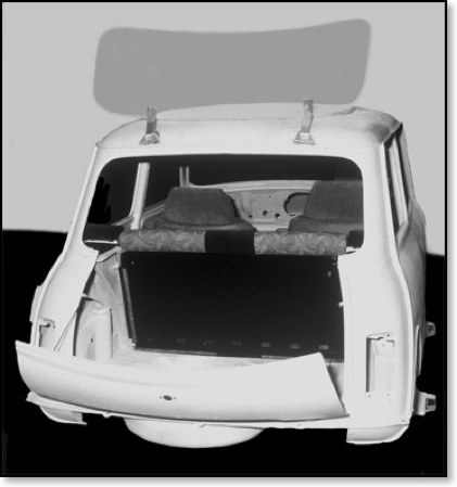
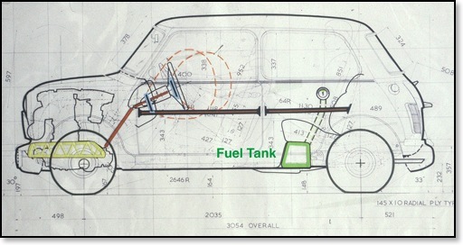
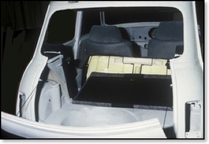
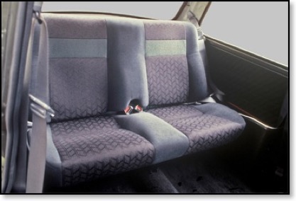
Luggage space was increased (more than doubled, in fact) by re-sighting the fuel tank into that ‘wasted’ space under the front edge of the rear seat, and by changing the rear subframe rear crossmember, so that the battery, spare wheel and whole boot floor could be lowered. We achieved nearly Rover 100 levels of boot space, amazing in a Mini!
The rear bulkhead was removed and replaced by a frame, that allowed for a split folding rear seat, based on modified Rover 100 components. A very practical arrangement, particularly as the rear of a standard Mini becomes almost impenetrable with larger than standard front seats!
The Drivers Ergonomics
Here, I was fortunate enough to have the assistance of Wyn Thomas (interior designer for Rover 200, Rover 75, etc). A pair of special front seats were made, using mainly Rover 100 components, and the jointed steering column was installed, again derived from Rover 100. This gave a much more normal driving position, but meant that the switches and minor controls were further away from the driver.
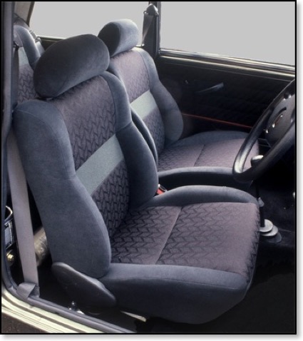
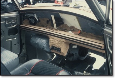
The above components were fitted into a scrap bodyshell, together with a new instrument pack (from a Honda Beat, looking more like a motorcycle instrument pack). A new interior design using Wyn’s sketches translated into a full-sized clay interior model, constructed inside the scrap bodyshell. A fibreglass ‘negative’ mould was taken off the clay, from which a ‘positive’ fibreglass fascia was made. This was trimmed and installed to give a complete interior buck.
Clay Stage 1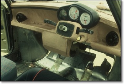
Clay Stage 2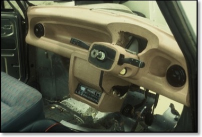
Clay Stage 3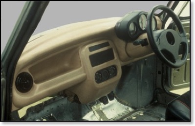
Final Clay Stage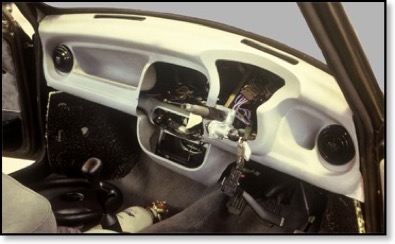
Fibreglass version of the clay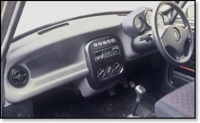
Final Version Painted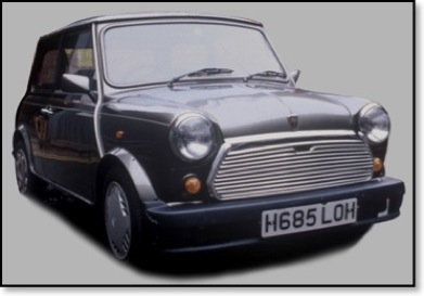
Final Car
Management Presentation
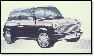
A senior management presentation was set up in the showroom at Canley. Exhibits were shown, along with a slideshow presentation showing their construction, the product strategy, test results, etc. Wyn created some lovely vehicle sketches and cartoons to illustrate the handout brochure.
The conclusion reached was that although the technical changes made gave a dramatic improvement and up-dating the product, it was effectively too late. The cost of engineering the changes, and the significant homologation difficulties that would have to be overcome (the original car pre-date much of this, such as crash testing), was all too much for the production volumes that Mini could now achieve.
The Minki-I exhibits were eventually scrapped.
_______________________
Minki-II
1995 arrived, and so did BMW! They were surprised that we had such a strong brand of Mini, but no plans to do anything with it. Plans for a new Mini were required, and a ‘competition’ was set up, for later on in 1995, to decide on the route forward.
It was decided that a part of that event should be a vehicle that represented what current Mini could have become if investment and development had been put into the Mini over many years. This vehicle would then act as a better benchmark than a standard current Mini for judging what the new Mini needed to beat.
Fortunately, all of the old Minki-I stuff had just been scrapped off, so a Minki-II was hastily required! I say fortunately, because in comparison, the Minki-II project was a very grand affair! By this time, our senior management had seen BMW in operation, and were impressed by the way that they did everything properly, with very high quality prototype vehicles, excellent engineering, etc. Minki-II had to live up to this standard. Great! It was a proper project, with designers and even a few bought-out parts!
I was seconded into Mike Pendry’s Experimental Vehicles dept, who did the design and build work, under my guidance. We used the Minki-I learning, together with a re-appraisal of the current Mini’s strengths and weaknesses.
As before, the engine was going to be a key issue, as there was not sufficient time (approx six months) to develop a running three cylinder ‘K’ series engine. It was decided instead to widen the vehicle just enough to get the standard ‘K’ series four cylinder engine in. This would also give a better driving environment, and whilst we were chopping the shell, we might as well lengthen it slightly as well, as we knew from Minki-I experience that we were going to end up with the front seats further back to suit the jointed steering column. It was important that the car still looked like a Mini, so a painted Mini bodyshell was sawn down the middle, and the two halves slid apart the calculated amount necessary to see if it still looked acceptable. The required extra width was 50mm, and the extra length was also 50mm. The look was acceptable in width, and also in length as long as the increase was in the doors.
The vehicle would have to be driven by the BMW hierarchy, and exhibit excellent levels of refinement. For this reason, the rear end changes (hatchback) were not made, as the body stiffness and water sealing issues would be too risky, anyway we still had the Minki-I photos.
Much of the Minki-II followed the Minki-I spec, especially the installation of the Rover 100 hydragas suspension, the ‘K’ series engine and 5 speed gearbox (although now wider and a four cylinder engine). The Minki-I fascia unfortunately had gone, and there was not time to recreate it, so a modified Rover 100 fascia, instrument pack and heater controls were installed, along with the Rover 100 jointed steering column and seats.
The bodyshell was expertly made by the Canley tinsmiths (who ended up as Gaydon tinsmiths, moving during this time). They used a production Mini bodyshell, taken off the production line before its roof was fitted (as per the convertible Mini’s), and “hot cross bunned” (chopped into four quarters!). New longer sills, cross-members, etc were made up to get back to one entity. Longer doors were made, wider bonnet and boot lid, and a special new wider and longer roof. This was made using an ‘egg crate’, which was a set of wooden formers, longitudinal and lateral, that gave the curvature of the roof. This was than opened up 50mm in each direction, blended in, and then used to mate together four oversized roof quarters into a new roof panel. The final bodyshell, painted in bright ‘flame red,’ was immaculate.
Suppliers made up oversized front grille, bumpers, seals and trim strips, glass panels, window winder mechanisms, etc. The fascia was cut and modified in-house, as was a new wiring loom. New inlet and exhaust manifolds were fabricated, this was needed as the engine had to be re-orientated, as normally the ‘K’ series engine leans forward by 15 degrees, in the Minki it had to be upright. This required new bolting arrangement at the bell-housing, also changes to the bulkhead cross-member to clear the new inlet manifold. It was for this reason that we chose to use the (then) top of the range ‘K’ series engine – the 1.4 litre MPi engine, on the basis that we wanted to start off with as much power as possible as we feared the new tighter packaged manifold system would lose some power (in the end, it didn’t), and also the power would be useful to fully exploit the new chassis. The alternator had to be re-sighted to clear the suspension tower, and the brake servo system ‘reversed’, so that it could be mounted on the left hand side under the bonnet. The distributor had to be driven by the front camshaft, rather than the rear camshaft.
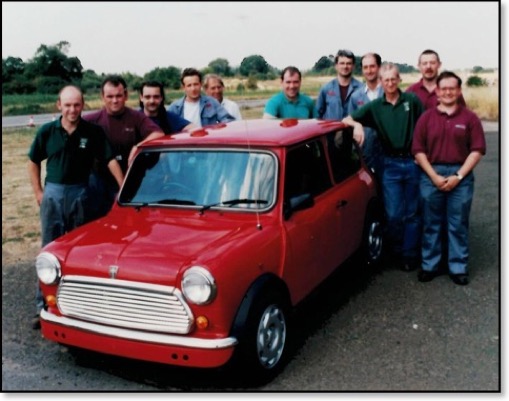
Some of the team who built Minki-2 taken at Gaydon Test Track.
The person on the right is Mark Ray team leader.
The vehicle was running a few weeks prior to the big ‘Mini Event’ run by Dr Reitzle, the BMW board member responsible for all product engineering, taking over the Gaydon Heritage Musuem,. It was arranged for Dr Reitzle to have a test drive of the Minki-II prior to the Mini Event at Gaydon. He was very complimentary of the vehicle, and the work that had been put in to achieving it.
The Mini Event at Gaydon
18th October 1995
At this very significant event, there were many exhibits and presentations. From the UK, there was the Minki-II, representing what the current Mini could have become. There was also the R59, Rover’s design for the new Mini, which included one with Hydragas and the other with conventional coil springs version. There was also the ‘Spiritual Mini’, and its bigger brother ‘Spiritual Too’. Whilst the main exhibits were fairly conventional arrangements, Spiritual was attempting to recreate the radical step made in 1959, and make something truly innovative. BMW presented a number of styling themes, using relatively conventional engineering. Their dynamic vehicles were based on Fiat Punto running gear.
Alex Moulton made a speech, able as he was to talk from first hand experience of working with Alec Issigonis on the original Mini, and the issues that were uppermost at the time.
At the end of the event, Dr Reitzle determined the route for the new Mini. Whereas Minki-II was too late (it should have been in production years ago), Spiritual was judged to be too early. BMW decided it needed something ‘now’, ready prior to the new millennium. It therefore had to be relatively conventional in engineering, with a striking but recognizably Mini appearance. It was to be a development of the BMW style, over the Rover developed package. Both hydragas and conventional suspensions were to be pursued in parallel, for around six months as it happens, until a clear decision could be made.
Minki-II Hydragas Development.
There now followed an intense amount of hydragas development, with the valuable assistance of Phil Turner, who was in charge of the chassis for MGF and MG TF, to prove whether the dynamics could be improved to current day standards.
Just like current Mini, hydragas had suffered from no real development for years, and was beginning to show its age. BMW had a poor perception of hydragas, mainly through their perception of Rover 100, which for them seemed biased towards ride rather than handling. As the interface to BMW on Chassis Concepts, it was my job to show whether hydragas could compare favorably with conventional spring / damper systems. This was done using measurements of ‘vertical dynamics’, ie measuring the stiffness and damping versus frequency for the complete vertical control system.
Alex Moulton organized many meetings at Dunlop, Coventry, where we all got together to discuss our findings, and decide on the next course of action. Dunlop measured the systems on their electro-hydraulic test rigs, BMW supplied samples of their current 3-series front suspension struts for comparison, we provided Rover 200 front struts, and through Alex we got new prototype hydragas parts made.
From these results we found that the BMW struts were not as good as they claimed, with much more frequency dependence of the out of phase damping component than they expected, whilst the hydragas units had insufficient low speed damping.
So from the technical data from the rig testing, a number of changes to the hydragas unit were made, which turned out to give dramatic improvements:-
1) Kevlar diaphragm. This gave a large increase in hydraulic bulk stiffness (ie, stopped it ‘ballooning’ under pressure) as well as a massive reduction in flexural stiffness (ie less hysteresis under suspension movement)
2) Disc type damper valve. This replaced the old fashioned petal valves, and resulted in better damper control.
3) Damper pack decoupler. With the greater diaphragm effectiveness, and the better damper pack, there was now too much high frequency damping. A conventional system uses rubber mounts at the end of the damper to give some high frequency small amplitude isolation. There now needed to be a similar feature in the hydragas unit. This was achieved by internally mounting the damper pack via rubber ‘O’ rings, with a carefully controlled pre-load.
4) Larger bore front to rear interconnection pipes, to allow greater peak flow requirements, but with a blow-off valve, to control low frequency vehicle pitch.
5) As with Minki-I, a good large bore pipe was required from displacer to front gas egg, as this has to cope with full suspension flow requirements.
6) Adjustable gas sphere pressures, system pressures, damper pack shimming and displacer pushrod lengths all allowed ‘system tuning’.
Many permutations were tested, both on rig-test and on the Minki-II vehicle. By this stage, we had got to a good stage of vehicle development, and needed to make a more extensive appraisal of the vehicle.
With BMW’s assistance, we took Minki-II down to the BMW test track at Miramas, southern France, and then on to Munich. In Miramas, we inadvertently got caught up with Reitzle and his first line assessing all the new BMW products, as they do each year with a string of armed guards on motorbikes. Fortunately, they soon realized that we were ‘the mad Englishmen’, and waved us out of their way.
Next, it was up to Munich, skirting around Switzerland. Being able to cruise at 100mph on the autobahns, without using full throttle, and still being able to speak easily was a unique experience in a Mini, as was the surprised looks on the Porsche drivers!
We drove the Minki-II into the BMW engineering Fiz building, where it was kitted out with a radio communication system. Then off to the local BMW test track with the BMW chassis engineers, for some handling assessments and violent lane-change manoeuvres. Most of the BMW engineers admitted it was hard for them to assess such a vehicle, as they were so tuned into BMW brand values and sizes of vehicles, and ‘Mini-ness’ was something alien to them!
Next day, we went on the autobahns out towards the Czech border, and used some of the quiet local roads there to make assessments. However, all the German roads are so smooth and well maintained compared to UK roads, and generally built with constant radius bends. They were in for a shock with the UK roads!
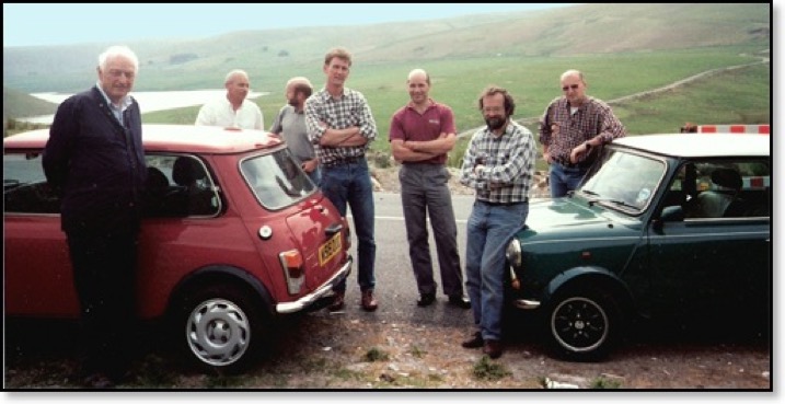
Next stage was to assess Minki-II, and a number of other Minis, back in the UK. A number of the BMW engineers joined us for a trip to Wales. Here, the Minis were even more in their environment, with the roller-coaster roads twisting and winding all the way. The BMW chassis development engineer rather disparagingly dismissed them as ‘Mickey Mouse roads’, but then started to understand why the cars were as they were. (He subsequently brought his family across for a holiday in Wales, as did other BMW engineers!).
I think it’s fair to say that the general conclusion of all of this vehicle assessment work was that the Minki-II was a more ‘grown-up’ Mini, in every sense of the word. There was more space inside the car, the driving position was more accommodating and comfortable, the car had much better performance and refinement, the ride was much more accomplished, mainly because it had got rid of those sudden vertical jolts of the standard Mini. The car was able to steer and handle without drama at higher speeds than a standard Mini, and yet overall still having a very clear ‘immediacy of response’ that characterizes Mini driving.
Eventually a decision had to be made as to whether the new Mini was going to use hydragas or conventional suspension. The BMW chassis guys were appreciative of the developments we had made, but gently allowed us to come to the realization that the durability proving and productionisation of the new hydragas developments would take it beyond the timescale of the vehicle programme.
The Minki-II vehicle then earned a well-deserved rest, going on display in the Heritage Museum at Gaydon, and the hydragas developments we had made looked for a new potential application.
THE END
My thanks to Tony Spillane for supplying all the information and pictures.