

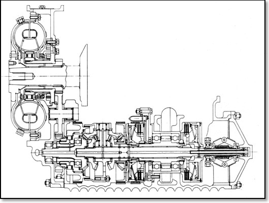
Mini-1100 AP Automatic Transmission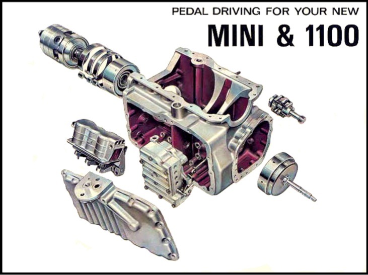
Exploded View
Information on the following article was sourced from an Automotive Products (AP) publication in 1967. AP was possible best known for its Lockheed brakes and Borg & Beck clutches etc. So when in 1965 at the Earls Court Motor Show, this ingenious system was announced, it caused quite a stir throughout the motoring world.
Considered by many to be the most outstanding technical development in the 70 year history of the British motor industry, this remarkable AP automatic transmission for small cars is not merely an enviable achievement for design and development engineer but is a complete break-through in volume production engineering and assembly techniques.
Development and Prototypes
It took 10 years of painstaking design and development work before the simple two-speed self-changing gear unit became the unique four-speed AP automatic transmission for small cars. This was a major advanced in producing a four-speed automotive gearbox that could be operated like a manual box. It must be remembered that this was nearly sixty years ago, and was unique because it operated in a very small space using standard engine oil. To reach this goal, involved much detail design work, long-term development, and teamwork from the start between designer and service engineer.
It all started in the early 1950s when the Company announced the 'Manumatic' transmission system. This was a semi-automatic two pedal system using a standard synchromesh gearbox in conjunction with an electro-pneumatically controlled centrifugal clutch. The 'Manumatic' system enabled the driver to change gear merely by selecting the gear he wanted without using a clutch pedal. Various car manufactures included it as an option with Austin fitting it on the A40-50 Cambridge. It did not catch on mainly because it was neither a manual or an auto, there were also some service problems.
A lot of knowledge was gained for this first product, and on the back of this, AP Group decided they would develop a fully automatic box for British and European manufactures. It was from 1955 onwards that AP started its highly secret investigation which they were confident would eventually lead to a fully automatic gearbox at that stage of an unspecified type. Early studies at Leamington Spa centred around spur gear layshaft boxes with multiple clutches providing power shifts between ratios. Inevitably a torque convertor had to be designed as this provides the only practicable means of coupling an automatic gearbox to the power unit. As it turned out the torque convertor was the only item which reached fruition at this stage for in 1956 an independent Belfast engineer, Mr Hugh Reid, approached the Company with a bevel gear device which he had designed as an overdrive unit; he suggested that the same device might form the basis for an automatic gearbox.
2 Speed version installed in a Humber Mark
The Reid system involved various cluster of bevel gears arranged as a planetary system. But the main drawback was that this basic system gave only two ratios, low and direct. It was only possible to change from direct to indirect drive by taking your foot of the accelerator. A decision was taken to married one of the Reid two-speed unit to the latest AP torque converter. The complete unit was then installed in a Humber Hawk which successfully completed close on 20,000 miles of development testing, although it was without any reverse gear! (must have made it interesting).
Two-speed transmission on test
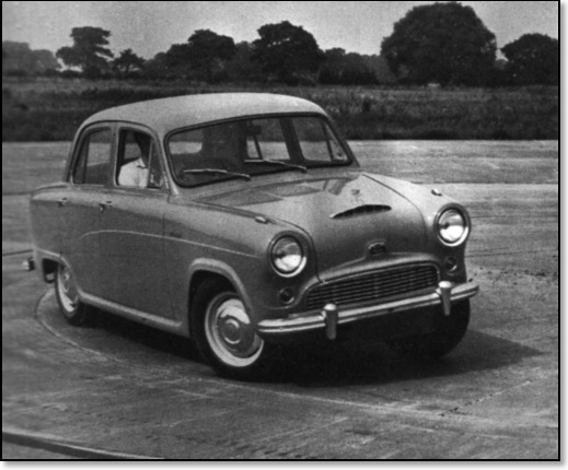
A50 Cambridge on Test
The next major development came in 1957 when, still within the Reid patent, two complete two-speed units were manufactured for test and installed in 1.5-litre Austin A50 Cambridge. These units, while retaining the weight control system (because of the patent), had the added refinements of a reverse gear and a system of dogs for connecting the drive to the output. The sheer simplicity of this early arrangement had much to recommend it. It had no complicated hydraulic system, and a centrally mounted selector lever made for very efficient dog engagement particularly when it was depressed, to brake the torque convertor turbine before engaging the dog drive. This level of simplicity ended abruptly, however when it was decided to build a three speeds version.
Two-Speed version installed in a A50 Cambridge
The two A50 Cambridge saloons eventually covered a total of 100,000 miles of severe testing. Over this distance not only did they prove the satisfactory operation with both the two and three-speed AP transmission units. It was decided to convert one so that engine oil could be circulated through the gearbox and pumped back into the sump. This gave the Group valuable advance information on the behaviour of automatics running in lubricating oil which was contaminated by products of combustion and other foreign matter. It was at the height of the A50 Cambridge testing programme that the BMC Mini was announced and its combination of a low capacity, modestly powered engine with a very compact transmission system offered a challenge which AP designers could not ignore. By December 1959 design work commenced on a fully automatic three-speed transmission system for the Mini based on the successful three-speed Cambridge unit.
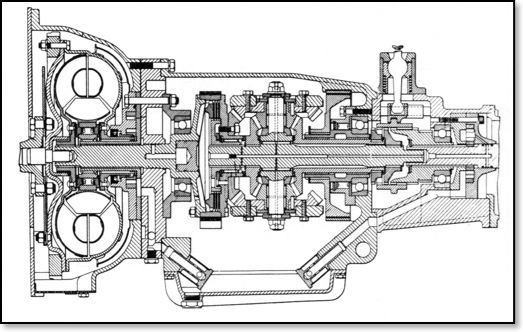
Three Speed Version
Three-Speed Version (Early Mini)
This three-speed unit was a complex little box, which retained the bulky double cone clutch assembly. With sucessful development testing, it was decided to demonstrate this to BMCs Technical Director Alex Issigonis. He was so impressed, that he immediately ordered a number of prototypes for test purposes. Soon after the four-speed version came along, this proved a winner with BMC as it utilised the full performance of the 850cc Mini yet gave the car the same performance as the conventional 4-speed manual gearbox while occupying the same amount of space beneath the engine.
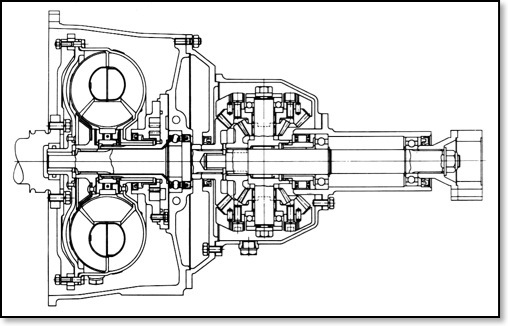
Four Speed Version
The new four-speed prototype transmission unit, after more development soon became the basis for the production version of the unit which was adopted by BMC for their million-selling Mini and 1100 models. Before this went into production, however, a number of significant changes had to taken place. In the first instance the four-speed unit retained the double cone clutch but it was
found that using this device in a small car with short, stiff drive shafts and no lengthy transmission shaft to absorb the torsional stresses proved to be a great problem so it was necessary to redesigned the unit, to incorporate hydraulically operated multi-plate clutches.
Another problem arose with the standard crankshaft, as at the point where the torque convertor is attached it was prone to fracture. Because of this it was necessary to complete re-design the torque convertor around an extended crankshaft. The two and three versions had a free wheel unit which was complemented by additional clutches for overrun braking. With the newer four speed version there was now not enough room for the free wheel unit, so in the end, the free wheel was abandoned and the transmission now included overrun braking on all ratios.
The prototype four-speed AP automatic transmission first appeared in an 850 cc Mini in 1962. All the units produced up to this stage had been built in a relatively small department at the Group's Leamington Spa headquarters. With BMC's decision to place a large order, meant that a large manufacturing facility had to be set up at Leamington for full-scale production work. Rather than build new factory premises AP decided that it would be more economical to transfer their self-contained Purolator filter division to premises in Bolton, Lancashire. So with the vacant factory space it was time to place orders for all the equipment needed to set up the new Automatic Gearbox Division. BMC would be suppling the following, the main sump and differential casings, and the bevel gear train, main shaft and intermediate gearing and main oil pump. All the various sub-assemblies and components for the transmission to be manufactured at Leamington.
It was estimated that to setup a machine shop to produce the components to support the orders placed by BMC would cost £1million. From day one it was decided to buy machinery from the very best available sources, regardless of their country of origin.
The production shop layout is planned almost exclusively on a component group basis so that all machines, heat treatment plant, inspection facilities and test plant appertaining to one particular component are adjacent to each other. All groups are equipped with their own air or electrical measuring and gauging instruments and manual operations have been reduced to an absolute minimum. Ninety per cent of the machines require only manual loading and unloading and the machine cycle is then automatically controlled, often with plugboard or
similar pre-set sequencing control methods. To reduce working capital the department's inventory is closely controlled to a weekly intake of materials and bought-out parts. As a result of adopting the best and very latest of modern production methods and techniques the department's output has steadily risen from 75 sets of components per week in September 1965 to 1200 sets a week less than two years later in step with BMC's ever-increasing production. The production could be quickly expand to over 2000 units per week which would be the optima capacity of the present plant layout.
Longbridge gears up for production
(Kings Norton)
It was decided at the time that no building on the Longbridge plant was suitable for the assembly of the automatic transmission, but it did have a unit on the Kings Norton Factory Centre on the Pershore Road. This had been used in WWII to assemble Jerrycans, and since then as a surplus machine store.
So plans were put in place to convert this rather dismal store into an ultra-clean factory using the very latest production techniques and machinery.
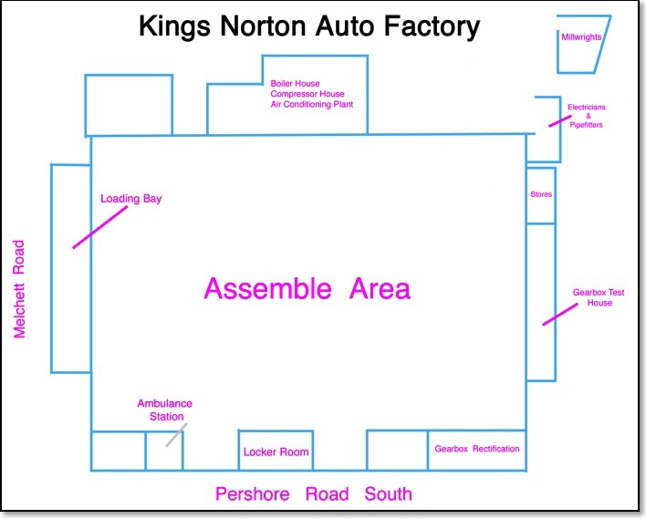
The Kings Norton Factory
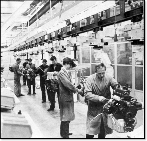
In the record time of twelve months BMC transformed the unit into a modern, high output factory for the production of complete Mini and 1100 engine/automatic transmission units. To do this BMC have had to spend £750,000 in redesigning the interior of the building, reflooring most of its 21,600sq ft, and installing all the assembly plant, test equipment and offices associated with the most modern present-day factory production techniques. The interior of the building is bright and airy with a degree of cleanliness not normally encountered in a factory, but which is essential for the assembly of the precision-made AP automatic transmission system. This cleanliness is maintained by an air conditioning system which feeds the main assembly area with a complete change of pressurised and filtered air 15 times every hour; also a complete ban on smoking in the area preserves this dirt-free atmosphere. Similarly, an interesting overhead conveyor system, with the units suspended on pendant arms, enables the floor to be kept in a clean, uncluttered condition. The new Kings Norton factory (designated Austin No 2 Factory) is arranged so that the transverse (or 'east-west') power unit is assembled on a moving track in the main assembly area while the transmission system is built in another area of the building. After inspection and test, the transmission enters the power unit assembly track where the two components are joined together and the whole engine/transmission unit moves on to inspection, test and despatch.
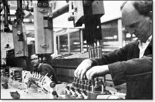
Engine assembly Process
Engine assembly starts with the introduction of the washed cast-iron cylinder block onto the assembly track, where it is secured to one of the overhead conveyor pendant arms. After a delivery and pressure test in a cabinet alongside the track the main oil pump is attached to the block and the unit moves on for the attachment of the crankshaft and its associated gearing. Between this point and the next assembly stage the pendant arm carrying the cylinder block is equipped with wire baskets. Whilst this is going on the cylinder head is built up.
Final stage in the assembly of the cylinder head
Cylinder heads are constructed in an overhead section of the shop on a flow-line basis wherein the washed head casting, ready machined, enters the line at one end and in four stages the valves, springs and collets are assembled, the various side studs and head studs are screwed in and then the camshaft and rockers are secured to complete the assembly. Each cylinder head is given a leak check (to prove the valve seating) on a rig in the department and a special vibrator rig is also used to give the valves an initial 'running-in' period and thus reduce tappet setting drift at the engine test stage. A set of engine block components are passed through a automatic degreasing plant; these items include connecting rods, timing gears, manifolds, end-plates and the like. The other basket contains non-washable items such as the starter, dynamo, coil and similar components. The final assembly phases include fitting the calibrated carburettor and its manifold, the rocker cover and the transmission 'kick-down' linkage. After introduction of the subsidiary components the whole central portion of the power unit is built up in stages along the assembly track until it is ready to receive the transmission assembly.
The transmission test department at Kings Norton contains four test rigs (three for production test and one for inspection rectification) specially developed to give the automatic transmission system a complete functional test in as little as six minutes.
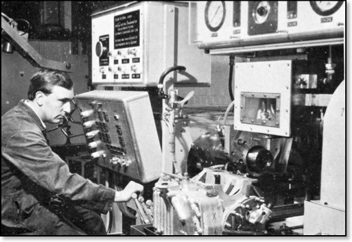
The rigs are driven by electric motors and incorporate a dynamometer and an auto/manual control system which controls the following test sequence. With the gear selector in neutral, oil pump delivery, flow and pressure is checked right through the unit including the valve block operation and delivery to the engine. In 'drive', gear-changing and load are checked in all gears at a light throttle setting; the motor input is varied by a rheostat. A similar check is then carried out under full throttle in each gear. A fourth test in 'drive' checks for slip in all gears by holding the output with a disc brake. Finally a tow-start test checks the auxiliary pump and its associated valves and sequencing ; this test is carried out by spinning the differential at 20 mph with the gear selector in third gear. Any failures during this rigorous test procedure are recorded and the unit is diverted to the rectification bay where it is stripped, examined and rebuilt so that it can pass the specified test on a similar test machine. Those which pass the test are loaded on an overhead conveyor and, identified by a Mini or 1100 'flag', are despatched to the engine assembly line.
The transmission units join the assembly line from a lift which lowers the units off the overhead conveyor and down to bench level. At this point they are removed and secured to the power unit while the empty gearbox carrier returns to the transmission test house for another load. With the gearbox secured, the engine assembly moves on to receive the torque converter and various engine components before the ready-made cylinder head is secured.
View of the pendent conveyor system on final engine/transmission assembly.
The engine test bay is a triumph in sound-proofing, for despite the fact that its ten booths are open at the sides and the whole bay is doorless, the noise level inside and out is negligible. Inside each booth a completed power unit is connected to a dynamometer via its final drive couplings and with fuel, oil and water connected (the latter being preheated to working temperature) and electrical connections made, the unit is subjected to a full, simulated road test lasting 15 minutes. The test is governed by a punched-tape programme, housed in a console above the power unit, and this varies the load on the engine whilst the operator governs the throttle setting by hand. Dials and indicator lights record the engine's performance and among these are two sets of lights, one signifying 'rich' or 'lean' carburettor setting, the other recording torque output and converter slip.
Should any of these lights indicate a fault the power unit, after disconnection, is automatically routed to a rectification bay outside the test area where the fault is diagnosed and corrected before it is re-directed back into the test bay.
The final production stage takes the power unit from the test bay to a rotary carrier - the 'carousel' - where the units are painted. Even this process is as advanced as the rest of the Kings Norton methods, for it is done electrostatically. As the paint spray leaves the operator's gun it is electrically charged so that the attraction between the paint and the engine mass ensures a uniform and semi-permanent covering on the unit. After painting it only remains for the units to be secured to transport cradles-for the short journey by road to the vehicle final assembly track at Longbridge, headquarters of the British Motor Corporation.
The Power Units are then transported to Longbridge for the Mini version assembled in CAB1 and the 1100/1300 models to CAB2, with some going down to Cowley.
______________
How does this automatic transmission work?
In place of the normal clutch a torque converter is bolted to the end of the crankshaft. Drive is transmitted by primary gears to the main bevel gear train in the transmission case. This is best described as a differential within a differential, and by holding different parts of the assembly through servo-operated brake bands the different gear ratios are obtained. Two clutches are used to complete the power transmission; one of these is used for all forward gears, supplemented by the second one when top gear comes into use; this second clutch also transmits reverse. The clutches drive onto the differential, whence conventional drive-shafts take power to the road wheels.
An oil pressure system operates the brake bands and clutches which are controlled by valves operated by cable from the quadrant-control in the car and by a governor driven from the auxiliary oil pump that rotates in proportion to road speed. The main oil pump runs with the engine, circulating oil to the torque converter and valve block as well as to the power unit. As one 'fill' of oil circulates in the whole unit, the need for regular oil are necessary along with a oil filter which has a larger capacity that the manual version. An extension of the throttle linkage provides additional bias for the governor and gives extra speed in the gears for accelerating, as well as the kick-down change facility.
The auxiliary pump pressurizes the circuit once the car is on the move even without the engine running, thus enabling the vehicle to be tow-started. The unit is astonishingly compact, taking up little more room than the normal manual transmission. The slightly more powerful engine (55 instead of 50 bhp on the 1100) is mounted a fraction higher in its compartment in a stronger, redesigned front sub-frame, with the result that an annular air cleaner surrounds the carburetter vacuum chamber in place of the normal overhead unit. The main advantage of any auto transmission system is that anyone can jump straight into the car and drive it properly, smoothly and safely from the word 'go'. Start the engine, pull the selector lever all the way back through its neat quadrant to the 'D' position, press the accelerator, steer and hey presto, you are off ! But there is much more to it than that, once the driver has settled down to the job, or rather enjoyment of exploiting the system to the full, in particular the unusual fully automatic/fully manual facility of this tiny AP 'magic' box.
-------------------------
Design for easy servicing
Servicing was one of the things foremost in the designers' minds when the production version of the AP automatic transmission was finalised. This accounts, in part, for the neat packaging of the system into self-contained units and for the comparative ease with which these units can be removed and replaced in the transmission case. Indeed so aware were the designers of the need for rapid and economical servicing that AP's experts from their Banbury Service and Spares Division were introduced to the system at the early production prototype stage. It was in these early days that the overall servicing policy was visualised when, together with their counterparts from BMC, AP's servicing organisation decided that it would best be maintained on an exchange unit basis. With some exceptions this is still the policy today, so that any damaged unit in the transmission system is removed from the vehicle and replaced by a new unit. The customer, of course, is given an allowance on the damaged part and the whole repair is performed with the minimum of delay and expense. At first it was thought that any unit in the transmission system which failed would need to be completely replaced.
However, after careful examination at AP's Banbury factory it was found that many of the various units could be repaired using a kit of spare parts. It is necessary to get various special service tools made to supply the agents. So a team comprised a service advisor from AP, one from BMC, and an expert from V. L. Churchill Limited, the company which manufactures servicing tools for BMC. This team spent some time at Banbury stripping and rebuilding the transmission system and performing every foreseeable maintenance job on the system before they finally arrived at a set of tools that could form the basic kit. The first tools to be decided upon were those which permitted easy removal of units from the transmission and those which ensured rapid and correct replacement of units. After this various tools were designed which would enable the mechanic to service selected units using an approved repair kit. The policy during this period was that the tools should be designed jointly by AP, BMC and Churchill, that the design must be accepted by BMC, and that the manufacture was the responsibility of Churchill. Naturally special tools are only one aspect of servicing which must be decided at an early date, another important item to be progressed as early as possible being the various technical publications. AP's Publications Department at Banbury had to familiarise themselves with the unit as quickly as possible so that eventually they were able to supply information to BMC for the Automatic Mini and 1100 owner's handbook and the BMC service and spare parts manual. In addition, the writers had to complete AP's own service diagnosis manual. People such as packaging specialists had to be shown the transmission in order that they could decide the most effective and efficient ways of packing and storing spare parts and of ensuring that the spares, whilst in store, remained in mint condition.
All this organisation has evolved into a regular routine wherein spares for the AP transmission components are packed and despatched from Banbury and distributed through BMC to their various retail outlets. Similarly any modifications to the AP components are covered by the Publications Department at Banbury who issue modification leaflets informing interested parties of the changes to the transmission system. Eventually AP's Banbury factory will undertake the servicing of all the transmission units of AP manufacture which are returned on an exchange basis.
A vitally important facet of any service organization's work is the instruction of personnel who will have to work on the Company product. This is true, of course, whether the product is new and revolutionary (as in the case of the AP transmission) or a well established and familiar line (such as Lockheed brakes, Borg & Beck clutches and the like). Thus, following the lead from BMC, the Service School at Banbury sent out letters detailing a three-day instruction course for mechanics on the principle, operation and maintenance of the unique AP transmission. These letters went to selected BMC service centres (other than direct BMC franchise holders, who are instructed by BMC themselves) and asked for names to be put forward for entry to the course. The response to the invitations was so overwhelming that within one month the year's course list was full. The courses opened during the first week in January 1967 and are held for three days every week. Although it was originally planned to have only six people on a course at one time, so that the instructor could give individual attention to each student, the classes have averaged nine students at a time. The course makes extensive use of coloured slides for instruction purposes and is divided up as follows: on the first day students are instructed in the principle and operation of the transmission. Day Two is allocated to the operation and servicing of the individual units, and Day Three is taken up with practical instruction in stripping, rebuilding, adjustment and fault diagnosis on the unit. During the course (which lasts for seven hours every day) all the students are given the opportunity of doing every job on the gearbox which is likely to be encountered in the garage. Unlike many similar kinds of courses there is no examination or certificate at its completion for, as the Chief Instructor says, "the valuable time taken in examining students can be better employed in further instruction".
Training service technicians
In addition to actual course instruction, knowledge of the gearbox and its operation can be spread in other ways, one of the most popular being from the lecture platform. Ever since the AP transmission first appeared the AP Group has been inundated with requests from professional bodies, technical colleges and motoring organizations for lectures on the 'magic' gearbox. To date Company representatives have presented lectures twice a month all over the country so that with a regular audience of 120 appreciation of the technical aspects of the transmission is growing rapidly.An important part of AP automatic transmission service, as with all other AP products, is field service wherein a trained factory engineer can be made available immediately to offer advice and practical assistance on the customer's own premises. Even though there are an estimated 40,000 Automatic Minis and 1100's in service in the UK this duty at present requires only one specialist who, along with other service engineers, is on call to any part of the British Isles. Normally requests for service advice go direct to BMC Service Limited at Oxford who deal with the matter either themselves or, if they feel the need, in conjunction with the AP service engineer. Calls which come direct to AP are dealt with by our own service engineer but always in consultation with the BMC Service Department. Similarly all automatic transmission service personnel keep in regular contact with the AP Leamington and BMC Kings Norton production plants to ensure a continuity of development in the overall servicing policy.
Pictures showing the various components made by AP.
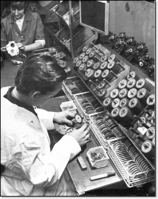
The auxiliary oil pump gears are sintered and only require grinding for thickness before assembly.
With the gears positioned in the pump housing their height is checked with a dial indicator.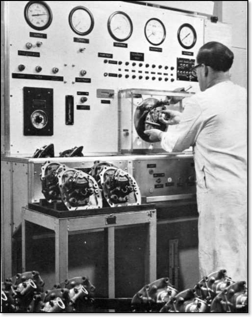
This test rig automatically checks auxiliary pump output and flow while
measuring movement of the governor at various speeds.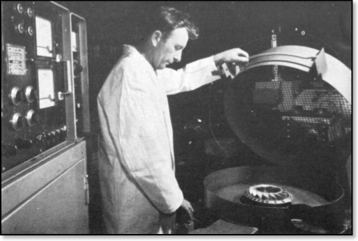
This balancing machine is connected to an electronic control circuit and panel which automatically
measures and records the amount - and angle – of unbalance in the convertor stator assembly.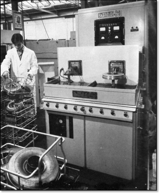
This automatic induction heater is used to harden collars and sleeves on torque convertor components.
The sleeve is heated to a predetermined temperature; then the assembly is dropped
into a cold quenching bath to complete the hardening process.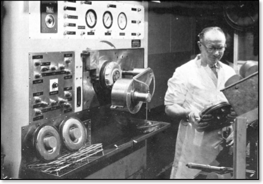
Every torque convertor is given a complete leak test and functional check under full stall conditions on this fully automatic test console. The hydraulic clamp Is lowering after completion of a test sequence.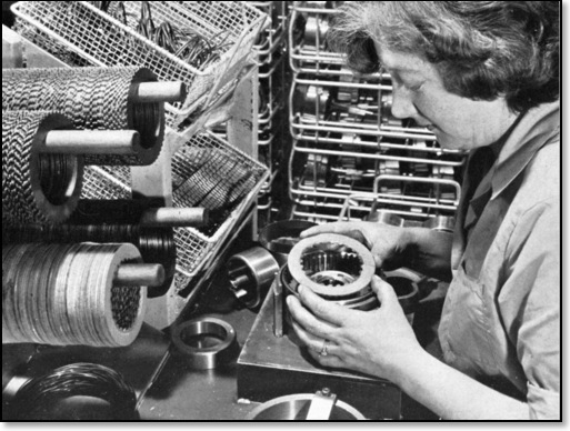
The automatic transmission clutches been assembled by hand.
______________________________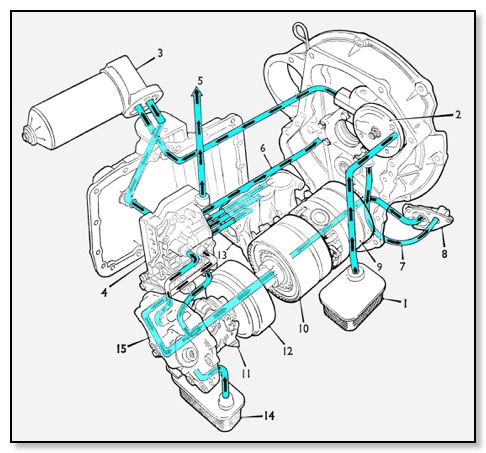
Showing the lubrication system and 'power flow'
1. Main oil strainer. 2. Oil pump 3. Oil filter assembly. 4. Valve block. 5. Engine oil feed 6. Converter feed pipe. 7. Converter to low pressure valve feed. 8. Low pressure valve 9. Gear train. 10. Top and reverse clutch. 11. Governor. 12. Forward clutch. 13 Servo unit. 14 Auxiliary pump oil strainer. 15. Auxiliary.
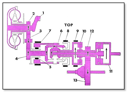
Mechanical Flow Diagrams
1. Crankshaft. 2. Converter output. 3. Idler gear. 4. Input gear. 5. One-way clutch. 6 Gear carrier.
7. Reverse band. 8. Third gear band. 9. Second gear band. 10. Top and reverse clutch. 11. Forward clutch.
12. Final drive pinion. 13. Final drive gear.
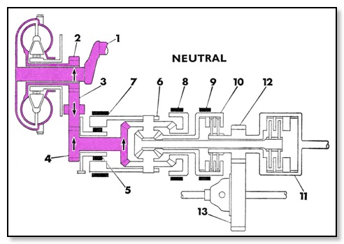
When in neutral all the bands and clutches are disengaged, therefore there is no drive to the final drive pinion.
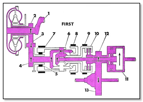
First Speed: In this ratio the forward clutch is applied and the one-way clutch is operative. The carrier is stationary, its reaction being controlled by the one-way clutch. The input bevel drives the planet wheels and the planet pinions drive the forward output pinion and shaft. Thus power is transferred through the planet assemblies to the mainshaft, forward clutch, and the output gear providing a ratio of 2.69 : 1
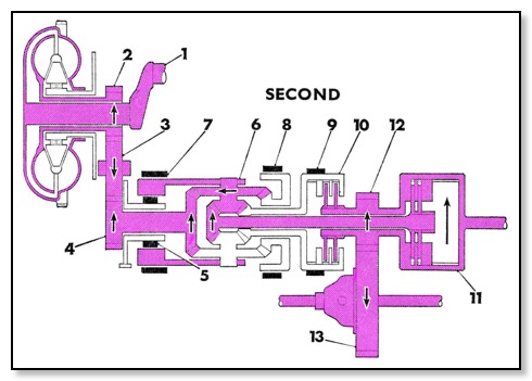
Second Speed: As for all forward gears the forward clutch remain engaged, and in addition the second speed brake band applied. This controls the reaction which is imposed on the reverse drive bevel when in this ratio. With the planet cluster orbiting around the reverse drive bevel power is transmitted from the input bevel through the planets to the mainshaft and provides a ratio of 1.845 : 1.
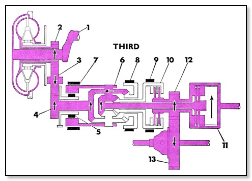
Third Speed: For this ratio the third speed bevel wheel is held by its appropriate drum and brake band, and in this case the planet clusters orbit around this gear. Like second speed, power is transmitted from the input bevel through the planets to the mainshaft and in this provides a ratio of 1.46 : 1
Top Speed: In addition to the forward clutch, the top and reverse clutch is engaged. This in effect locks up the bevel gears and the reduction gear assembly then rotates as one unit to provide direct drive.
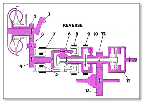
Reverse: In this ratio the carrier is held by the reverse band -- (the one-way clutch being inoperative because the reaction is in the opposite direction to first speed) In addition the top and reverse clutch is engaged,. The input bevel wheel drives the planet wheel and the planet pinion drives the reverse drive gear. Thus power is transmitted through the planet assemblies to the top and reverse clutch and thence to the final drive pinion to provide a ratio of 2.69 : 1.
If you need spares for the above transmission, Click on this link. https://jpat.co.uk/