

Austin produced its own aeroplanes in the early years, and in the First and Second World Wars produced complete aeroplanes, along with suppling components for other manufactures.
At the end of the article is a video showing the production of the Hurricane and flight testing from Austin's own airfield. (Running time 6 mins)
Herbert Austin decided to set up an aircraft design department in 1917, to develop its own range of light planes for sale.
Austin Designed Planes (AFB 1)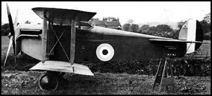
This plane incorporated some ideas put forward by the flying ace Capt. Albert Ball, VC, DSO, MC (He was killed when only 20 years old). It was from this tie up that the first aircraft produced went under the code name AFB1. The plane was actually designed by C H Brooks and flew for the first time in July 1917.
It was of wooden construction with fabric covering, and was powered by a 200hp Hispano-Suiza V8 liquid-cooled engine. Austin's designed a machine-gun that would fire through the centre of the propellor shaft and was patented in December 1915, some six months before Vickers came up with a similar idea called the interrupter gear which was fitted to 7.7mm Lewis machine gun firing through the hollow propeller shaft, and a similar weapon on a Foster mounting above the upper wing centre section.
As originally built, the sole prototype of the AFB.1 had slightly sweptback wing surfaces and conventional single-bay bracing. The plane had a maximum speed of 138 mph and could climb to 10,000 feet in under 9 minutes, with a service ceiling of 22,000, this gave it slightly better performance than the SE5. During the course of development new upswept surfaces accompanied by revised inter-plane bracing of two-bay form were introduced. These modifications were carried out on the prototype and was flown on 17 September 1917. It would appear that the programme was cancelled soon after.
Specification:
Wing span: 29 ft. 9 in Length: 21 ft 6 in Height: 9 ft 3 in Wing Area: 289 sq ft
Weights Empty:1562 lb. Loaded: 2077 lb.
Performance Max Level Speed: 138 mph
____________________
Austin Greyhound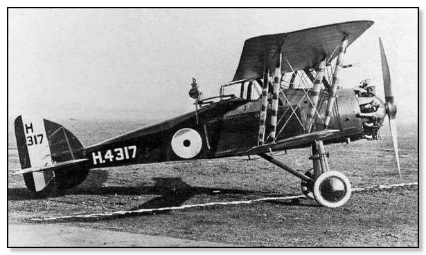
Austin Greyhound H4317
J Kenworthy
J Kenworthy designed the Greyhound tandem two-seat fighter-reconnaissance aircraft which could be a potential successor to the Bristol Fighter. The first prototype was not completed until after the Armistice of 1918 owing to difficulties with its 320hp ABC Dragonfly I nine-cylinder radial engine. Flight testing eventually commenced in May 1919, and three prototypes were built and flown, but soon after no further development was undertaken. Armament comprised two fixed synchronised 7.7mm Vickers guns and a single 7.7mm Lewis gun on a Scarff ring in the rear cockpit.
Specification:
Wing span: 39 ft. 0 in Length: 26 ft 8 in Height: 10 ft 4 in Wing Area: 389 sq ft
Weights Empty:1839 lb. Loaded: 3031 lb.
Performance Max Level Speed: 130 mph
____________________
Austin Osprey Triplane (AFT3)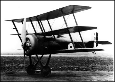
This plane which was designed in 1917 tended to have two names, the Austin AFT3 or Osprey Triplane of which only one was made, it was intended to compete with the Sopwith Snipe. The Osprey was of wooden construction with fabric skinning, the six wings were interchangeable. A 230hp Bentley BR2 nine-cylinder rotary engine supplied the power. The armament comprised two fixed 7.7mm Vickers machine guns which are synchronised to fire when the blades of the revolving airscrew are not in line with the gun barrels. Also a one semi-free Lewis gun of similar calibre is mounded to the centre-sectionof the middle wing, to fire upwards over the top wing. The Osprey was flown for the first time in February 1918, but performance proved to be inferior to that of the Snipe, and construction of the other two prototypes was abandoned.
Specification:
Wing span: 22 ft. 7 in Length: 17 ft 5 in Height:10 ft 7 in Wing Area: N/A
Weights Empty: 1100 lb. Loaded: 1883 lb.
Performance Max Level Speed: 118 mph
____________________
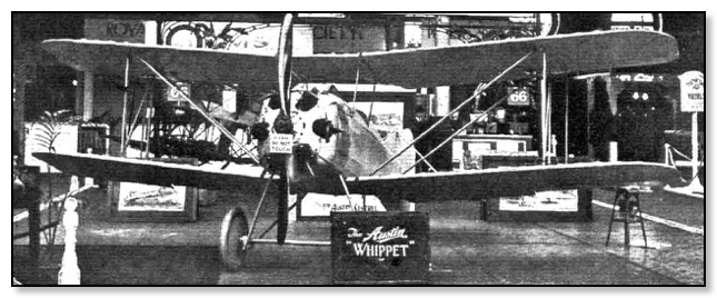
Austin Whippet
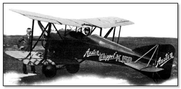
The Whippet was designed by John Kenworthy working for the Austin Motor Co. Ltd. Aero Division. It first flew in 1919, it was a Single seat biplane with an open cockpit aft of the wings. The wings were made to fold back, and this made it possible to house the aircraft in a shed measuring just l8ft long, 8ft high, and only 8ft wide. They were upswept, slightly staggered, un-tapered, it had equal span and equal chord wings of wooden structure. The Steel tube fuselage with fabric covering mounted on lower wing with a braced tail-plane and single fin and rudder. Landing gear was the cross axle type with tail-skid.
At the Aero Show in 1919 a prototype was exhibited with a 2-cylinder horizontally opposed engine. For the production version power would be supplied by one 45 hp Anzani six-cylinder air-cooled radial driving a two blade propeller. It had a top speed of 95 mph and could cruise at 80 mph. With a low landing speed of just 30 mph it was claimed that it only needed 150 yards to stop. It was hoped that the price would be about £450, which at the time was the price you would pay for a medium-sized car. An experienced RAF pilot remarked at the time that he could teach anyone to fly her in ten minutes.
 (Flight)
It had its first public showing at the International Aero Exhibition Olympia on Stand 66 from the 9th - 20th July 1920, by this time the price had risen to £500. Five were actually produced, three remained in the UK with one going to Argentine and the other to New Zealand. As only a few sales materialise, mainly because amateur flying simply had not caught on, it was decided to cease production.
 (Flight)
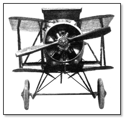
Front view with wings folded
Specification:
Wing span: 21 ft. 6 in Length: 16 ft 3 in Height:7 ft 6 in Wing Area: 134 sq ft
Weights Empty: 580 lb Loaded: 810 lb
Performance Max Level Speed: 95 mph Initial Climb 5,000 ft in 9 min Flying Time 2 hr
Landing speed: 30 mph
____________________
Austin Kestrel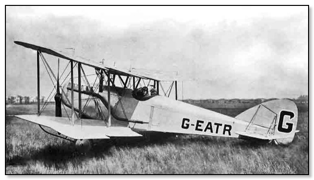
The Kestrel was next on the scene, this was designed by J Kenworthy, in his early days he had worked with Geoffrey de Havilland at the Royal Aircraft Factory. The first experimental prototype Whippets were made during the first half of 1919. This new plane would have a steel tube fuselage and have the unique feature that the wings could be folded up thus making it easy to store in a garage or a barn. Power for this two-seater plane would by a 160hp Beardmore engine. The Air Ministry, to stimulate interest among manufactures, arranged an Air Trial at Martlesham airfield near lpswich in August 1920. with a total Prizes money of £641.000. The company decided to enter the Kestrel. Actually the Kestrel came third in its class, winning £1,500. Because orders were not forth coming, this sole Kestrel was eventually broken up. So Herbert Austin decided to close down the aircraft business and concentrate on the cars.
Advert 1920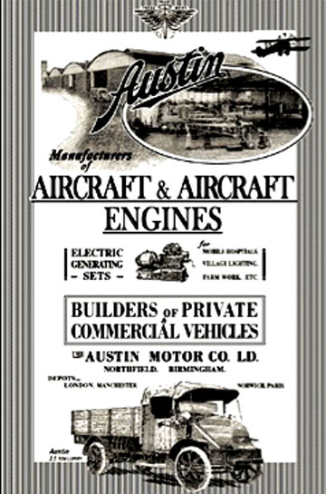
____________________
World War I Planes
In World War I, The Austin Motor Company (Aircraft Division) was given contracts by the Government to produce aircraft for the war effort.
Bristol F2B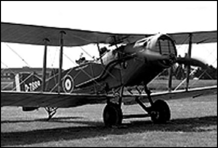
The Bristol Fighter was a two seat fighter and reconnaissance plane of the first world war. The Bristol F.2 Fighter was a two-seat biplane fighter and reconnaissance aircraft of World War I flown by the Royal Flying Corps. Despite being a two-seater, the F.2B proved an agile aircraft that was able to hold its own against single-seat scouts. Having overcome a disastrous start to its career, the F.2B's solid design ensured that it remained in military service into the 1930s and surplus aircraft were popular in civil aviation.
Specification RE 8 version
Wing span: 25 ft 10 in Length: 25 ft 10 in Height: 9 ft 9 in Wing Area: 405 sq ft
Weights Empty: 2,145 lb. Loaded: 3,243 lb.
Powered by 1× Rolls-Royce Falcon liquid-cooled V12 engine, 275 hp
Performance Max Speed: 123 mph at 5,000 ft Max. Rate of Climb: 889 ft/min Service Ceiling: 18,000 ft
Armament: Guns:1× .303 in (7.7 mm) forward-firing Vickers machine gun in the upper fuselage and 2× .303 in Lewis guns in the observer's cockpit
Bombs: 240 lb (110 kg)
Crew: 2: pilot & observer/gunner
It appears that according to the records the Austin Motor Co made four.
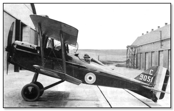
RAF SE 5 - SE 5A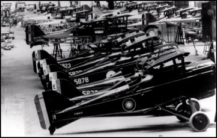
The SE5 was initially designed by ex-Daimler engineer Fred Green of the Royal Aircraft Factory, Farnborough, with a team of three which consisted of John Kenworthy, the chief draughtsman, Henry Folland, who was head of the design group along with test pilot Major Frank Goodden, whose crucial instruction on test flights enabled improvements to be made, but was tragically killed while on one of these test flights! It was the dedication and skill of this small team, that put the aircraft together and made it a dominant influence in the skies.
SE5 stood for Scout Experimental and was regarded as the most successful plane produced by this firm. The design brief was to produce a plane that was easy to fly and that its characteristic enabled the Royal Flying Corps to entrust the plane to relatively inexperienced pilots. The final product met all its targets and although not as manoeuvrable as the Sopwith Camel, it was noticeably faster and quieter. But although less agile for dog-fighting it was capable of 138 mph and easily out manoeuvring the German planes. Powered by a 150 HP Hispano-Suiza V; the SE.5 entered service in April 1917. A new more powerful engine was adopted, a 200 HP Hispano-Suiza, so leading to the SE 5A and only minor changes were made to the rest of the plane. It was mid 1917 that the new model arrive in service. One main weakness was the unreliability of its engine and by the limited effectiveness of Constantinesco synchronizing gear. It was the first Allied scout with 2 machine guns: a Lewis gun on a Foster-mount on the top wing, and a side-mounted Vickers gun in front of the cockpit.
The total number made of the SE 5 & SE 5A was 5,205 of which the Austin Motor Co. made 1550 of the SE 5A version. In one week in 1918 over 60 of these Scouting Experimental machines were accepted by the Royal Aircraft Factory after test flights from the Longbridge flying ground.
Austin Built S.E. 5A (1917), Trentham Building on the Right
Specification SE 5A
Wing span: 26 ft 7 in Length: 20 ft in Height:9 ft 5 in Wing Area:257.5 sq ft
Weights Empty: Unknown Loaded: 2,048 lb.
Performance Max Level Speed: 132 mph at 6,500 ft Max. Rate of Climb: 765 ft/min Service Ceiling: 20,000 ft
Armament was a forward-facing synchronised 7.7mm Vickers machine-gun, and Lewis gun installed on top of the centre section of the upper wing; four 18 kg. bombs.
____________________
RAF RE7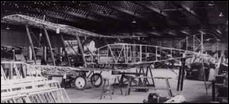
Longbridge Production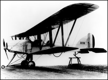
The Austin Motor Co. Ltd produced 52 of the RE 7 version and 300 RE 8 to the RAFs specification.
The R.E. 7 was quoted as been the most useless aeroplane ever made for the following reasons. It had a quoted top speed of 82 mph, but it very seldom exceeded 60 mph and its stall speed was just under 50 mph. With such a small difference between these speeds it was very easy to stall and spin out of control, also take-offs, landings and manoeuvring in the air very difficult. A member of the Royal Flying Corps. said the RE7 was "a pig - on a windy day a boy on a bicycle could pass it." Only 250 were built, it came armed with a forward firing machine gun mounted oblique to the aircraft to avoid the propeller. This made it very difficult to hit anything, as the aircraft had to be crabbed to one side when aiming at another plane. The observer could not stand, or turn around like in later aircraft, so a machine gun in the back was nearly ineffective as the observer had to aim it by leaning back and swivelling the gun while looking over his shoulder.
Along came the RE 8 version but by all accounts it wasn't much better.
Specification RE 8 version
Wing span: 42 ft 7 in Length: 27 ft 10 in Height:0 ft 0 in Wing Area: 00000 sq ft
Weights Empty: xxxx lb. Loaded: 2,678 lb.
Powered by the 150 hp RAF 4a engine
Performance Max Level Speed: 102 mph Max. Rate of Climb: 340 ft/min Service Ceiling: 13,000 ft
____________________
World War II Planes
FAIREY BATTLE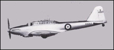
The Fairey Battle was designed by the Fairey Aviation Co Ltd at their factory in Hayes. It was designed to meet the requirements of Air Ministry Specification P 27/32 which had been issued in April 1933. The first prototype K 4303 made its first flight on 10th March 1936. This two-seater medium bomber had a low-wing all metal cantilever monoplane. The fuselage was a oval section all steel structure. Tail unit was also a metal cantilever monotype with the fin and elevator fabric covered. Main landing gear was retractable with the a fixed tail wheel. Power came from the Rolls-Royce Merlin III twelve cylinder Vee liquid-cooled supercharged engine rated at 1,035 hp with a three bladed variable pitch airscrew. It had a crew of two, pilot who could fire the machine gun in the starboard wing. Bombs were stowed in four cells in the wings. The rear gunner operated a machine gun in the rear cockpit.
Specification:
Wing span: 54 ft Length: 42 ft 4 in Height:15 ft 6 in Wing Area: 422 sq ft
Weights Empty: 6,647 lb Loaded: 10,792 lb
Performance Max Level Speed: 257 mph at 15,000 ft Service Ceiling: 25,000 ft Range: 1,000 miles
The Austin Motor Co Ltd at Longbridge was given a contract to build 1029 planes at the new shadow factory East Works in 1938. The first plane off the production line had the following Ref. No L4935. A further contract was placed for 200 planes, making a final total of 1229.
By August 1940 over eight hundred and sixty had been produced, some of these were supplied as kits to the following countries, South Africa, Canada and Australia.
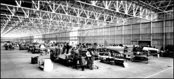
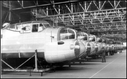
Fairey Battle production starting up in East Works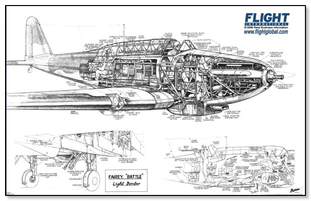
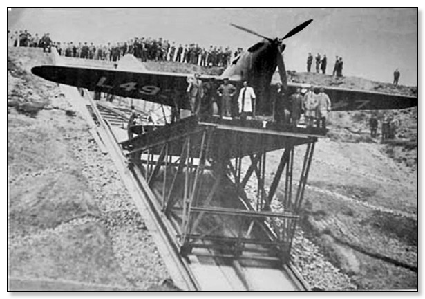
The first Fairey Battle (L4935) built at Longbridge 1937
(Please note the plane is normally facing the bank)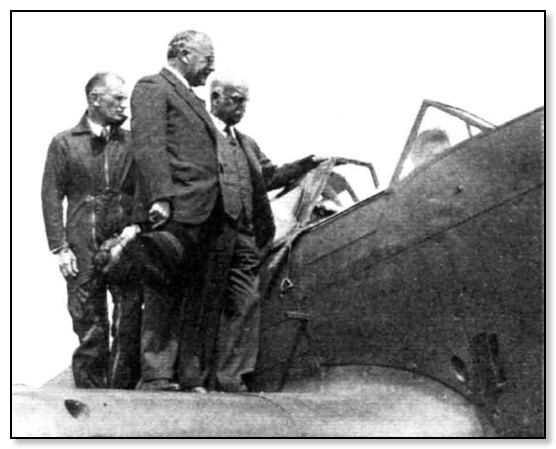
First Fairey Battle been inspected.
Sqn. Ldr. T H England (Test Pilot) Sir Kingsley Wood & Lord Austin
The last Fairey Battle built 5 Nov 1940 (V1280)
King & Queen visit East Works May 1939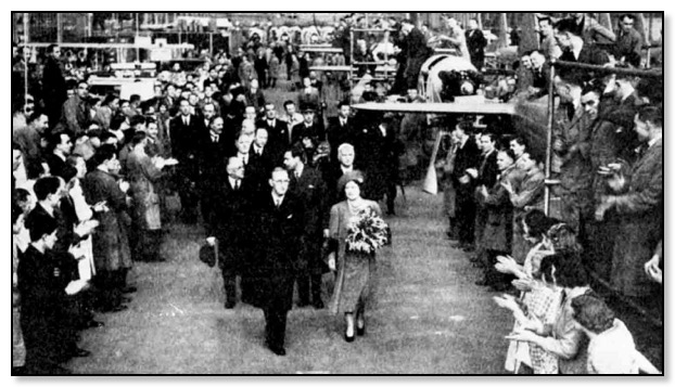
The King and Queen stepped from the royal train at Longbridge sidings and a short while later were watching the various parts of the air frames for the Fairey Battle bombers being produced. The King had a long talk with Mr G Ledgard, general manager of the factory about the shadow scheme.
Speaking to workers along the assembly lines, congratulating one on the way he was carrying out his task. He then visited a section where the testing of engines was so loud, that workers had to wear special ear plugs. The King was offered cotton wool but didn't use it.
By August 1940 over eight hundred and sixty had been produced, some of these were supplied as kits to the following countries, South Africa, Canada and Australia.
_________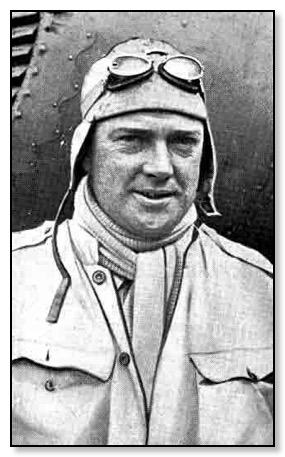
Captain. Neville Stack
6 September 1938
Chief Test Pilot - Captain Neville Stack Appointment
Captain T. Neville Stack has been appointed chief test pilot to the Austin Aircraft Works at Longbridge, near Birmingham, where Fairey Battle medium bombers are now being constructed. He returned only 17 days ago from Turkey, where he has been engaged for some time in delivering British aircraft. giving instruction to Turkish pilots in the handling of them, and unofficially advising the Turkish Air Ministry on the organization of civil air lines.
As a pilot and as an air superintendent, Captain Stack has a distinguished record. He made the first flight by light aeroplane to India in 1926, in company with Mr. B S Leete. The flight occupied nearly two months. but both the Cirrus Moths arrived safely and together at Karachi. A little later he became chief instructor to National Flying Services, and in 1935 he was appointed air superintendent to Hilllman's Airways.
Fairey Battle Crash Lands at Longbridge
On the 25th July 1939 a Fairey Battle produced in the East Works had taken off from the works airfield with the Chief test pilot Capt. Neville Stack (aged 42) who lived in Kings Norton and a mechanic Harold Crawford (aged 35) from Lickey End.
The plane which was coming into land from the railway side of the airfield. According to eyewitnesses the aeroplane had been put through various vigorous tests, including power diving and looping. As he was preparing to land, one wheel of the retractable under carriage failed to drop into position. The pilot gained height and circled round trying to shake the wheel free, but with no success. So Capt. Stack decided to try and land on one wheel. As he made his approach over the railway embankment a sudden loss of altitude put the plane in jeopardy, so as to avoid a head on crash he swung it round so that the wing took most of the impact and it crashed into the embankment just feet away from the airfield, the time off the crash was put at 6.45 pm.
The plane had its back broken and the engine and cockpit was damaged. The plane slipped a few feet down the bank and came to rest with its nose facing towards Barnt Green. The works fire tender and ambulance rushed to the scene, and Captain Stack and his mechanic were pulled out. Capt. Stack waved to the rescue party as they approached, although he must have been in great agony with both his legs broken. Crawford, however was unconscious suffering from fractures of an arm and leg and severe scalp wounds. They were taken by ambulance to Selly Oak Hospital, and relatives were speedily informed.
Hoses were played on the damaged plane to check any outbreak of fire, ropes were fastened to the wreckage to prevent it from sliding down the embankment on to the railway. Later cables were substituted for the ropes and the plane was removed on Thursday morning.
23 February 1949
Obituary. Capt. Neville Stack
Captain T Neville Stack, AFC., who in the period between the wars was one of the leading British pioneers in long distance aviation, was, killed yesterday, in a, road accident near Karachi, according to Reuter. He was 52.
Thomas Neville Stack was born on April 1, 1896, and was educated at St. Edmund's; College. He joined the Army in 1914 and three Years later transferred to the RFC. and served with 212 Squadron. After demobilization he worked as an instructor at the London and Provincial Aviation Company until 1921 when
he rejoined the RAF. and served in Iraq and elsewhere until 1925, when he returned to civilian life and joined the Lancashire Aero Club as chief instructor. In company with Mr. D. S. Leete he made the first light aircraft flight from England to India from. November 15, 1926, to January 8, 1927, and afterwards made a number of flights between European capitals.
A little later be became air superintendent and chief pilot of National Flying Services and in 1938 chief test pilot at the Austin Aircraft Works at Longbridge near Birmingham. For some time during the 1939-45 war he was air adviser at the War Office and later in the war was commissioned in the Fleet Air Arm. After Commanding squadrons, he was appointed Staff. Air Transport Officer to the Flag Officer (Air), East Indies. After the war he was general manager of Hunting Air Travel Limited and last May was appointed manager of the new Pakistan Airways.
____________________
HURRICANE
The Hurricane was design by the Hawker Aircraft Ltd which had its main factory at Kingston. Under the code name of F.36/34 it first flew on the 6th November 1935.A single seat fighter with a wing that is described as a low wing cantilever monoplane. Wings were of two spar metal construction with metal skin. The main fuselage frame was constructed of steel and aluminium alloy tubing, formed into an oval shape. This was then covered with metal panels in the forward sections with fabric stretched over the wooden sections at the rear. Landing Gear was the retractable type which was hinged to the front spar and retracted inwards and slightly backwards, the tail wheel was non-retractable. The pilot sat in an enclosed cockpit over the wing. The one Rolls-Royce Merlin XX twelve cylinder Vee liquid cooled engine which was rated at 1,185 bhp driving a three blade constant speed airscrew. Twelve Browning 0.303 in machine guns mounted in the wings.
The first Hurricane produced at Longbridge flew on the 8 October 1940
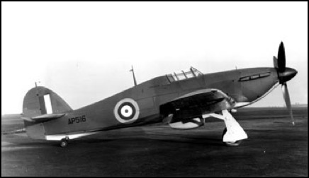
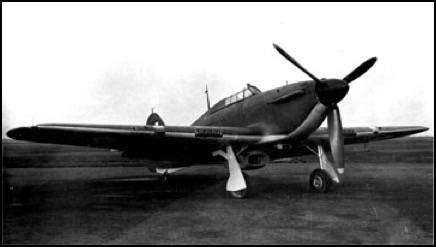
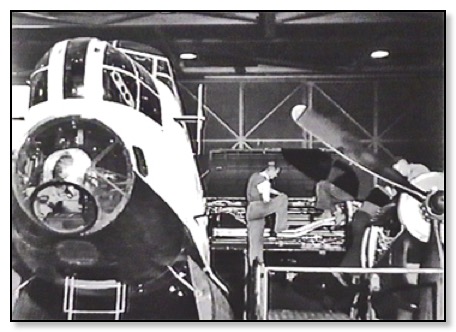
Austin built Hurricane on the works airfield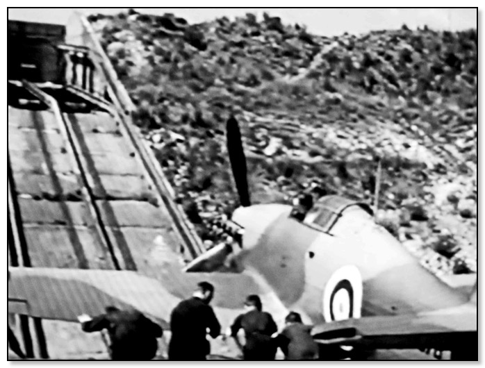
Hurricane ready to be lifted from the Flight Shed to the Airfield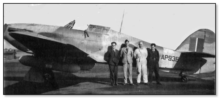
The last Austin built Hurricane MKIIB at Elmdon AP936
Specification IIB
Wing span: 40 ft Length: 32 ft 3 in Height:13 ft 1.5 in
Wing Area:257.5 sq ft Weights Empty: 5,640 lb Loaded: 8,250 lb
Performance Max Level Speed: 340 mph at 21,500 ft Max Rate of Climb: 2,950 ft/min Service Ceiling: 40,000 ft Range: 470 miles
The Austin Motor Company produced 300 Hurricanes probable the IIB version
____________________
Shorts Stirling Bomber
The Short Stirling was the first of the four-engined bombers to fly, the prototype taking to the air in May of 1939. However its undercarriage collapsed on landing and it was not until February, 1941 that the aircraft flew its first operation against the enemy. Tragically, the aircraft was needlessly limited at its conception. The engineers at Short's were faced with the restriction that the wingspan had to be less than one hundred feet so that it could fit into the standard RAF hangars of the day. This resulted in poor high altitude performance and a low ceiling. At low altitudes however, the Stirling was the fastest of the heavy bombers.The Avro Lancaster was designed by A.V. Roe and Co Ltd at the Newton Heath factory Manchester.
Specification Mk I:
Wing span: 99 ft 1 in Length: 87 ft 3 in Height:22 ft 9 in
Weights Empty: 46,900 lb Loaded: 70,000 lb
Performance Max Level Speed: 255 mph Service Ceiling: 16,500 ft (Max. Load) Range: 2,330 miles
Powerplants: Four 1,500 hp Bristol Hercules XI 14 cylinder, sleeve valve air cooled radial engines
Armament: Eight .303 Browning machine guns, nose turret (2), dorsal turret (2), tail turret (4), 17.000 Pounds of bombs
The first production Stirling rolled off the assembly line in August 1940
Crew: Eight
Specification: Mk III
Wing span: 99 ft 1 in Length: 87 ft 3 in Height:22 ft 9 in Wing Area:
Weights Empty: 43,200 lb Loaded: 70,000 lb
Performance Max Level Speed: 270 mph Service Ceiling: 16,500 ft (Max. Load) Range: 2,330 miles
Crew: Seven
Powerplant: Four 1,650 hp Bristol Hercules VI or XVI air cooled radial engines
Armament: Nine .303 Browning machine guns, nose turret (2), dorsal turret (2), tail turret (4) and underfuselage hand held mount (1), 17,000 Pounds of bombs
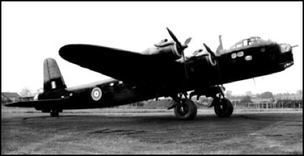
An Austin assembled Stirling Bomber
____________________
Avro Lancaster
The first prototype BT 308 was originally known as the Manchester III. Various modifications were made and the the second prototype DG 585 made its first flight on 13 May 1941. The first production Lancaster I Ref. L 7527 flew on the 31 October 1941, the main difference from the prototype was a more powerful engines and addition of dorsal and ventral turrets with the loaded weight increased from 50,00 lb. to 60,00 lb.
Avro Lancaster was a four engined heavy bomber with a mid wing cantilever monoplane. The two spar wing structure ribs were aluminium alloy pressings and the entire wing is covered in an aluminium alloy skin. Ailerons have metal noses, and fabric covered rear of the hinges. The fuselage was an all metal oval structure. Tail unit was an all metal cantilever monoplane type with twin oval fins and rudders. All metal structure. Tailplane, fins and rudders are metal covered, elevators covered with fabric. Main landing gear, with the wheels retracting into the inboard engine nacelles.
Power can from four 1,280 hp Rolls-Royce Merlin XX twelve cylinder Vee liquid cooled engines fitted with three bladed constant speed airscrews. Provision for a crew of seven, with a bomb aimer in the nose below the front gun turret. Above and behind is the pilots position and rear of them is the fighting controllers position. Further down the fuselage is seating for the navigator and the radio operator. Then we have the upper turret and the tail turret. The three powered turrets had eight 0.303 in Browning machine guns between them. Bomb compartment could accommodate 8 tons of bombs.
Specifications:
Wing span 102 ft. Length: 69 ft 4 in. Height: 20 ft. Wing Area: 1,297 sq ft
Weights: Empty 37,000 lb. Loaded 68,000 lb.
Performance Max Speed: 287 mph. Max rate of climb 250 ft/min. Service Ceiling 19,000 ft. Range 3,800 miles.
Austin Production
Austin Aero received a contract No 2827 late 1942 to supply 150 MK 1 Lancaster's for delivery between March 1944 and April 1945 almost three a week. From April 1945 the contract was for 150 MK VII to be completed by September 1946 which works out at about 5.8 planes per week. After this a further 30 MK VII were required between November 1945 to January 1946, giving a grand total of 330 planes.
The MK VII was a version that was only made at Longbridge. It incorporated the following Austin design changes, electric turrets and undercarriage modifications.
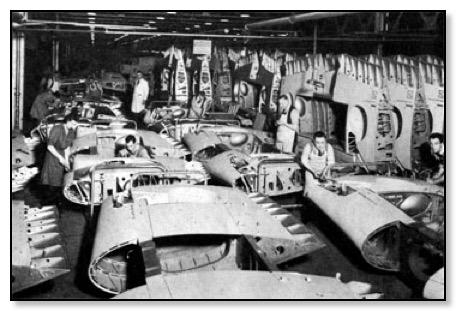
Fuselages lined up ready to be transported to Elmdon
Because of the short runway at Longbridge both the Stirling and Lancaster could not fly out from the factory airfield. So they were built as kits in East Works and then the various parts such as fuselages, wings etc. were transported to Austin's other Shadow Factory.
Because of the large sections taken by trailer, much of the street furniture en-route had to be removed, including a road cut straight through a roundabout in Kings Norton.
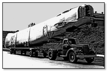
Stirling on-route to Elmdon
Austin's second Shadow Factory called Aero Works Frames where Mr C R Sharp was Personal Manager. This was situated in Marston Green on the other side of the railway line from Elmdon Airfield. It was opened for flying in May 1939 and operated by the Air Work Ltd, which held a Elementary and Reserve Flying Training School. In early 1941 the Air Ministry formally requisitioned the Airfield.
So the kits were assembled and complete aircraft were then towed over a temporary railway bridge. They were then taken into another hanger for pre-flight tests. From here they would be flown to the various bases round the UK by the pilots of the Air Transport Auxiliary (ATA) who were mainly female.
The picture above shows assemble of a Lancaster in Austin's own Hanger at Elmdon. Other suppliers of components including engines, landing gear etc, would be delivered direct to the hanger. In 1942 Austin was given an order for MK VIIs, these were the final production version, which were equipped with a American Glenn Martin dorsal turret with 0.50 inch guns.
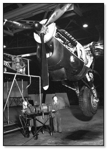
Testing the Landing Gear on a Lancaster (Elmdon)
(
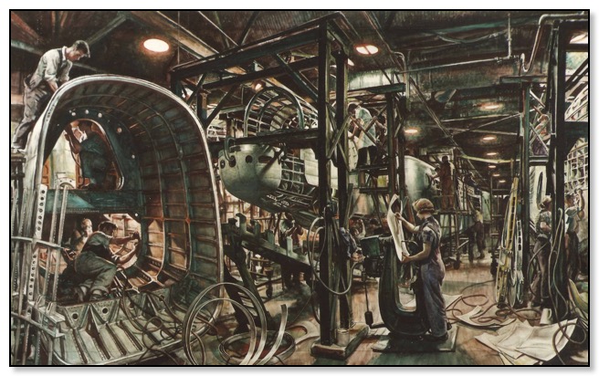
Dame Laura Knight, DBE, RA, famed for her theatrical, especially ballet and circus pictures, tells the story in her autobiography 'The Magic of a Line'. She reveals that her hearing has never been quite so keen since her Longbridge days. She worked in the midst of 20 drills, and 'their sound never left my ears even when I went back to Harold (her husband) for the week-ends'. A WARNING In the Longbridge chapter of her book, published last year, Dame Laura says: `I was asked to design a poster as a warning against the fires that—mainly through carelessness—were destroying many factories engaged in the war effort, and I went to the Austin works at Longbridge where Mr. (later Sir) Leonard Lord (now Lord Lambury) gave me every facility.
While making studies for this poster I conceived the idea of making a water-colour study of the actual construction of a Stirling bomber; it was impossible to paint in oil because of the confusion of different lighting. `It has to be a big picture, the fuselage of the bomber measured 31 feet.' Dame Laura says the shop steward who helped her was a former paper-hanger employed on war work and he 'joined many sheets of Whatman's "hand-made" (a rough-faced paper) together for me and pasted them down on an enormous board.
Lord Lambury, President of BMC (then Mr. Leonard Lord, Deputy Chairman and Joint Managing Director of the Austin Motor Co. Ltd.) later purchased the picture for the company and it hangs today in the entrance hall of the Administration Building. But first A. J. Munnings, then President of the Royal Academy, had the picture hung in the academy's summer exhibition of 1944—among the oils, although it is a huge water-colour.
Hung in the Royal Academy's summer exhibition of 1944—now in the entrance hall of the Administration Building, Longbridge. Its value, untested in the auction rooms, is estimated at £1000.
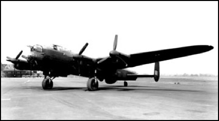
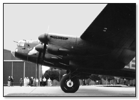
Austin built Lancaster at Elmdon Airfield 1941.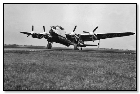
Austin Lancaster - NX 751 built in 1942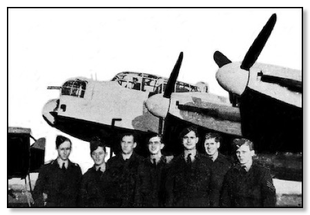
The Crew of NX 751 based at RAF Swinderby in Lincolnshire. The plane is painted black and white for Operation Tiger Force, a planned offensive on Japan, which never took place because the Japanese surrendered after the A-bomb attack. "The pilot (third from the left) is Frank Spillane, the father of Tony Spillane, who worked at Longbridge and was responsible for the Minki projects."
__________________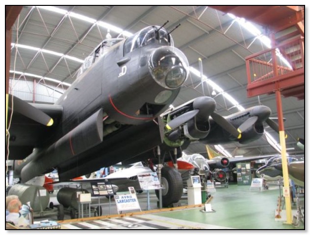
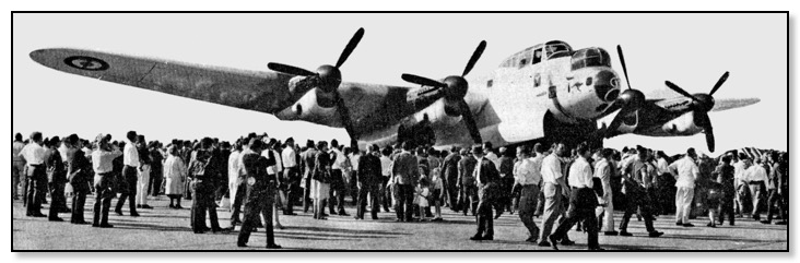
Lancaster NX 622 in the RAAFAWA Museum Australia
This MK VII Lancaster built by the Austin Motor Company did not see active service, only doing 7 flying hours with the RAF. In 1951 it was converted into a maritime reconnaissance aircraft for the French L’Aeronavale, first based in Lann Bihove, Brittany, but later moved to Noumea, New Caledonia. But in 1962 was retired from service and donated to the Air Force Association. For many years it was displayed outside at Perth Airport. With the opening of the Museum it moved into the North Wing on March 17th 1983. After undergoing extensive restoration it was put on display in WWII squadron colours.
For more information and pictures visit the RAAFAWA museum.
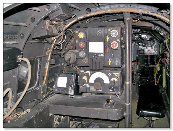
Wireless Operator's Position ----------------- RAAFWA - - - - - - - -
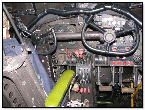
Cockpit - - - - - - - ---- - - - - - - - - RAAFWA - - - - - - - -
__________________
Austin produced parts for other aircraft
Bristol Beaufighter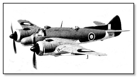
The Bristol Aeroplane Company decided that there was a need for a two-seat all-metal fighter using components from the Beaufort torpedo-bomber. The first prototype R 2052 was complete and ready for its maiden flight when the Air official Spec. F 17/39, the plane then first flew on 17 July 1939. With government order placed a new factory was built at Weston-super-Mare with the first production plane flew on 20 February 1941. The Beaufighter eventually equipped 52 RAF squadrons, giving outstanding service during World War II, in particular as a night-fighter and torpedo-bomber. It continued as a night-fighter until 1943, with the last aircraft a TT10 staying in service with the RAF until 1960, nearly 21 years after the type's first flight.
Specifications Mark VI
Wing span 57 ft. 10 in Length: 41 ft 8 in. Height: 15 ft. 10 in Wing Area: 503 sq ft
Weights: Empty 14,600 lb. Loaded 21,600 lb.
Performance Max Speed: 333 mph at 15,600 ft Climb 7-8 min to 15,000 ft Service Ceiling 26,500 ft. Range 1,480 miles max.
Crew: Pilot, Gunner and Radar operator
Production of parts for the Bristol Beaufighter
____________________
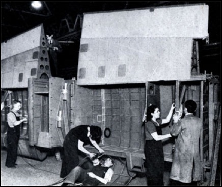
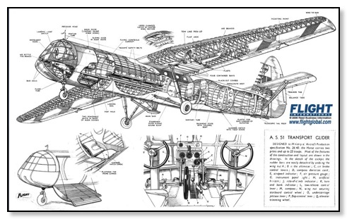
AIRSPEED HORSA AS.51 & AS.58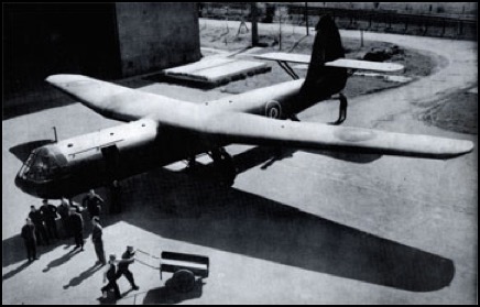
The Airspeed Horsa was designed by Hessell Tiltman for Airspeed to Specification X.26/40 which was to make a troop-carrying glider. With an all-wood construction the Horsa had been designed so that parts could be made by various manufactures who did not normally make aircraft, but had the necessary skills. The various parts were brought together for final assemble. The first of two prototypes had been assembled at Fairey's Great West Aerodrome with the first flight on September 12, 1940, behind a Whitley Tug. Another five more prototypes were built and tested.
The Airspeed Horsa MK I production version which could carry 20-25 troops was ordered by the Air Ministry. A total of 1,461 were made of which 300 fuselages were built by the Austin Motor Co. Wolverton was chosen for for the manufacture of the wings. No factory produced aircraft completely from start to finish. This was to prevent production being totally destroyed by a German air rail.
AS51 Horsa MK I specification
Crew 2 Wingspan 26.8 m Length 20.4 m Height 5.9 m
Wing area 102.6 sq. m Empty weight 3797 kg Takeoff weight 7031 kg Max. speed 241 km/h Cruise speed 161 km/h Payload 25 passengers
A further development in 1943 took place with a Mk II version called AS 58. This had a hinged nose and reinforced floor to carry vehicles; twin nose wheels, and twin tow-rope attachment moved from under the wing to the nosewheel strut. A total of 1,271 were produced with the Austin only making 65.
AS58 Horsa MkII specification
Crew 1 Wingspan 26.8m Length 20.7m Height 6.2m
Wing area 102.6 sq.m Empty weight 3797 kg Takeoff weight 7144 kg Max. speed 241 km/h Cruise speed 161 km/h Payload 25 passengers
Both the MK I & MK II could also carry a modified jeep or a 6 pounder cannon and no passengers. Later development of the MK II provided the glider with a hinged nose for easier access for large loads. A grand total of 3,655 of these reliable aircraft were provided in the war to ferry the airborne troops.
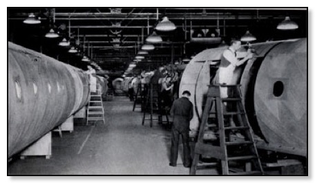
Austin Fuselage Production at West Works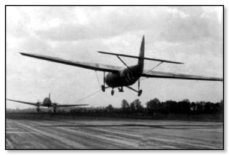
Horsa Takes Off
____________________
Miles Master MK I - MK II - MK III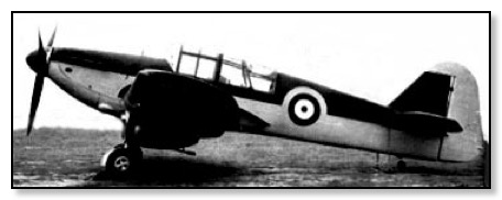
Miles Master MkI
The Miles Master was an advanced trainer which used the Miles M9 Kestral as its base, to cover the RAF Specification 16/38 which had been issued in June 1938. The MkI first flew in March 31 1939, in all seven prototypes were delivered to the RAF and a production run of 900 were produced. Various modifications were carried out, one been that the upward hinged canopy was replaced with a sliding version. Wings span was reduced from 39ft to 35ft 9in. Just over twenty were fitted with six 0.303in Browning guns in wings as emergency fighters. MK II was armed for practice firing with a single fixed forward firing Vickers .303 machine gun and could be armed with small practice bombs. The MK III main change was that the Bristol Mercury engine was replaced by a Pratt & Whitney.
Total produced of the MK I was 1,748 MK II & MK III combined figure was 1,554
Specifications Mark I
Wing span 39ft. 0 in Length: 30 ft 5 in Height Not know
Wing Area: 235 sq ft Weights: Empty 4,370 lb. Loaded 5,573 lb.
Performance Max Speed: 226 mph Cruising speed 160 mph at 10,00 ft Endurance 3hr
Powerplant Rolls Royce Kestrel XXX 715hp engine
Total production 1,748
MkII
Wing span 35ft.9 in Length: 29 ft 6 in Height Not know
Wing Area: 235 sq ft Weights: Empty 4,293 lb Loaded 5,573 lb
Performance Max Speed: 242 at 6,000 mph Range 393miles
Endurance 1.8hr
Powerplant Bristol Mercury Bristol Mercury XX 870hp radial piston engine,
MkIII same as MkII but a change to a Pratt & Whitney
Wing span 35ft.9 in Length: 29 ft 6 in Height Not know
Wing Area: 235 sq ft Weights: Empty 4,293 lb Loaded 5,573 lb
Performance Max Speed: 242 at 6,000 mph Range 393miles
Powerplant Pratt & Whitney 825hp R-1535-SB4G Twin Wasp Junior
Production of Miles-Master parts
Austin produced a total of 1,100 wings and centre-sections as shown above.
Austin Motor Company - Longbridge
Record of Aircraft built -1916 to 1946
For Royal Flying Corps. (WW1)
| Date | Type | Serial Numbers | Batch | Comment |
| 1916 on - | RE 8 | A3169 – A3268 | 100 | |
| A4261 – A4410 | 150 | |||
| 1916 - 17 | RE 8 | B5851 – B5900 | 50 | Delivery not confirmed |
| SE 5A | B8231 – B8580 | 350 | ||
| 1917 - | SE 5A | C8661 – C9310 | 650 | 26 supplied to U.S. Air Service |
For Royal Air Force (WW1)
| 1918 - | SE 5A | E5637 – E5936 | 300 | |
| SE 5A | F7951 – F8200 | 250 | Several supplied to U.S. Air Service | |
| 1918 - | Austin AFT3 Osprey | X15 – X17 | 3 | Only X15 built |
| 1919 - | Austin Greyhound | H4317 – H4319 | 3 | H4317 delivered to Martlesham on 15/5/19 |
| Bristol F2B fighter | H5940 – H6519 | 600 | Siddeley Puma engines Only 2 confirmed deliveries. | |
For Royal Air Force (WW2)
| 1937- | Fairy Battle mk 1 | L4935 – L5797 | 863 | |
| 1939- | Fairy Battle mk 1 | R3922 – R4054 | 100 | |
| 1940- | Fairy Battle T.T. 1 | V1201 – V1250 V1265 – V1280 | 66 | |
| 1940- | Short Stirling mk 1 (S29) | W7426 –W7475 | 50 | |
| W7500 – W7539 | 40 | |||
| W7560 – W7589 | 20 | |||
| W7610 – W7639 | 30 | |||
| 1940- | Hawker Hurricane mk 11b | AP516 – AP550 | 35 | |
| AP564 – AP613 | 50 | |||
| AP629 – AP648 | 20 | All except AP516 shipped to U.S.S.R. | ||
| 1940- | Hawker Harricane mk 11b | AP670 – AP714 | ||
| AP732 – AP781 | ||||
| AP801 – AP825 | ||||
| AP849 – AP898 | ||||
| AP912 – AP936 | 195 | Aircraft up to AP879 sent to U.S.S.R. | ||
| 1940- | Short Stirling mk1 mk111 (S.29) | BK592 – BK628 | Mk 1 | |
| BK644 – BK647 | 41 | |||
| BK648 – BK667 | Mk 111 | |||
| BK686 – BK727 | ||||
| BK759 – BK784 | ||||
| BK798 – BK818 | 109 | |||
| 1941- | Airspeed Horsa mk1 (AS51) | DP714 – DP726 | Glider | |
| DP739 – DP777 | ||||
| DP794 – DP841 | 98 | DP725 transferred to USAAF | ||
| 1941- | Short Stirling mk 111 (S29) | EH875 – EH909 | ||
| EH921 – EH961 | ||||
| EH977 – EH996 | ||||
| EJ104 – EJ127 | 120 | EH897,Eh950,EJ106 converted to Mk IV | ||
| 1941- | Airspeed Horsa mk 1 (AS51) | HG736 – HG770 | Glider | |
| HG784 – HG819 | ||||
| HG831 – HG880 | ||||
| HG897 – HG944 | ||||
| HG959 – HG989 | 200 | |||
| 1942- | Airspeed Horsa mk 1 (AS51) | LF886 – LF923 | Glider | |
| LF937 – LF963 | 65 | 20 transferred to USAAF | ||
| 1942- | Short Stirling mk 111 (S29) | LK375 – LK411 | ||
| LK425 – LK466 | ||||
| LK479 – LK521 | ||||
| LK535 – LK576 | ||||
| LK589 – LK624 | 200 | 33 converted to Mk 1V | ||
| 1942- | Avro 683 Lancaster mk 1 | NN694 – NN726 | ||
| NN739 – NN786 | ||||
| NN798 – NN816 | 100 | NN801 became Mk V11 prototype | ||
| 1942- | Avro 683 Lancaster mk1/V11 | NX548 – NX589 | B Mk 1 | |
| NX603 – NX610 | 50 | |||
| NX611 – NX648 | B Mk V11; NX611, NX622, NX664 and NX 665 still exist in museums in 2003 | |||
| NX661 – NX703 | ||||
| NX715 – NX758 | ||||
| NX770 – NX794 | 150 | |||
| 1943- | Avro Lancaster B mk V11 | RT670 – RT699 | 30 | |
History of Known Surviving Austin built Avro Lancaster
NX 611 (East Kirby Airfield, Lincolnshire). 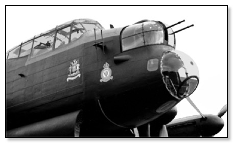
NX611 was built at Longbridge, on 16th April 1945, put into storage, and in 1952, it was one of 54 Lancasters sold to the French Naval Air Arm, (L’Aeronavale) for £50,000 each as part of a 1951 NATO arrangement. It was designated WU-15 (Western Union). In June 1961,it joined Escadrille 9S (Surveillance), in Noumea, New Caledonia.
On 15th April 1964, it accompanied Lancaster NX665 (WU-13), on delivery to the RNZAF, from New Caledonia to Auckland, New Zealand, returning to New Caledonia, with the crew of NX665.
Lancaster G-ASXX/NX611 was presented by L'Aeronavale to the British Preservation Group 'HAPS' (Historic Aircraft Preservation Society), based then at Biggin Hill, Kent. After its epic flight from Australia in 1965 the aircraft remained at Biggin until 30th March 1969, when it was flown to the former USAAF airfield at Lavenham, Suffolk, under its new ownership with 'Reflectaire Ltd'.
NX611 arrives back at Biggin Hill
After years of negotiation, it was acquired by the Panton brothers, in Sept 1983, who have set up a museum in memory of their brother Christopher Panton , killed on the Nuremberg raid in 1943. The brothers, Fred and Harold have spent vast amounts of time and money, restoring it to a condition where it regularly gives taxi-ing demonstrations at their museum, on East Kirby airfield, Lincolnshire.
For more information visit this website https://www.lincsaviation.co.uk/home.cfm
NX665 was delivered to the RAF on 30th June 1945, in a tropical form for Far East Operations, and was later put into storage at 38 MU LLandow, until 1951. In 1952, it was sold to the French L’Aeronavale and became WU – 13 on 23 May 1952. It served with Flotilla 10F in Brittany, then Flotilla 25F, transferred to Escadrille 56S in February 1959 at Agadir, Morocco. It returned to Le Bourget airfield, Paris in June 1961,and overhauled. Together with NX611 (WU–15) and NX664 (WU-21), it was flown on 12 July 1962 to Tontouta airfield, Noumea, New Caledonia, arriving on 28th July. It served in New Caledonia, until it was presented to the RNZAF, and delivered to Auckland, New Zealand on 15th April, 1964, accompanied by NX611, who returned the crew to New Caledonia. After a demonstration flight round North Island, New Zealand, it was eventually placed in the Museum of Transport & Technology, (MOTAT), Western Springs, Auckland. It had flown 2348 hours.
It has been repainted in RAF colours, the portside as SR – V; PB 457, representing NZ squadron 101 based at Ludford Magna in August 1944, (PB457 was lost on23/24 February 1945 in a raid on Pforzheim), and the starboard side as AA –O; ND752 representing NZ squadron 75 based at Mepal, Cambridgeshire, (ND752 was lost on 20/21 July 1944 on a raid on Hornbury in the Ruhr). A hanger was built for it in 1987/8
NX664 (WU-21) was also sold to the French L’Aeronavale in 1952, transferred from France to New Caledonia in July 1962, cannibilised for spares, and eventually returned to Le Musee deL’Air, at Le Bourget airfield, Paris, here it was undergoing restoration in 1992.
NX622 (WU-16) was also sold to the French L’Aeronavale, and delivered to Escadrille 9S (Surveillance) on 1st May 1957 at Lann Bihove, Brittany, and then to Noumea, New Caledonia. It eventually ended up at The Air Forces Association, Perth, Australia,where in 1992, it was restored
____________________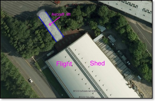
Picture Google Earth
I have shown the location of the Aircraft Lift.
Click on the Play Button to see a Video on the production of Hurricanes
and flight testing from Austin's own airfield.
(Running time 6 mins) May take a few seconds to load
PLEASE NOTE
If you are unable to see the PLAY Button, you need to update your software.