

Austin’s built Transfer Machines
Although starting off with a centre gear change, this was changed to the steering column, to bring it in line with the saloon in autumn 1951.
Mr Horace Holbeche, was Chief General Superintendent of Jig and Tool Design at Longbridge, and was responsible for the design and manufacture of the Austin Transfer Machines and Unit Machines. Through his expertise “The Austin” was able to automate the machining of the major engine components which kept costs down. He was born in 1901 and was a pupil at Kings Norton Secondary School (later Kings Norton Grammar). On leaving school he went to work at “The Austin” and stayed there all his working life, retiring early at the age of 67 because he could not agree with the policies of Lord Stokes. He was mortified that a company like BMC should effectively be taken over by Standard Triumph.
This article uses extracts from a paper presented jointly by Mr Holbeche and Mr F Griffiths, who was Chief Project Planning Engineer, to the Coventry Section of the Institution of Production Engineers on Tuesday November 16th 1954.
How it all started
One of the most pressing problems facing production engineers in the mid 1950s and which is still the case today. Was the need to manufacture articles more cheaply, and in ever greater quantities. Only if costs are kept down can a company sell at a price which will stand up to increasing competition at home and abroad. The motor car industry is one in which competition is fierce, and one in which costs must be kept low in order to bring a semi-luxury article within the reach of all. It is therefore, an industry which must be forever trying to make "something for nothing".
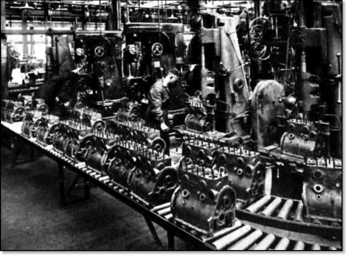
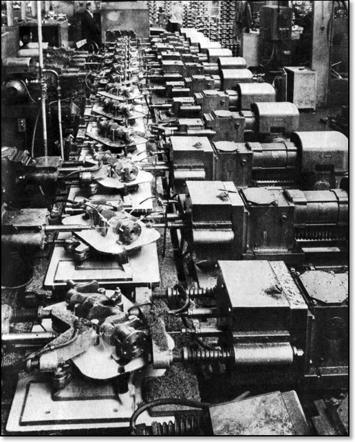
Showing how individual standard single machines were linked together.
In the early 1950s machine tools and production methods had not really changed. Because in the war years it was safer to use the money available to invest in known methods of production. It must be remembered that the main costs in producing even the smallest component are two-fold, raw materials and labour costs. Taking the raw material cost such as a castings or forgings you are looking at a cost of about £45 per ton (1950 prices), and resold for scrap at about £5 a ton. We are thus paying £40 per ton for metal which we do not want, and which costs us a lot of money in labour and capital costs to remove. To give an instance of what this can amount to, here are some figures for the material wastage’s with some of our components.
For every 2 tons of metal put into the Forge not much more than 1 ton finishes up as the machined product. For every 2 tons of castings poured approximately 1 ton finishes up as a machined product. For every 3 tons of bar put into the Automatic Shop only 1 ton emerges as the finished product.
The amount of money spent per year both in Capital and Labour, for useless work, is therefore very considerable. Fortunately, we are now beginning to receive some benefits from improved methods of casting and forging due to shell moulding, and investment processes in the foundry, squeeze forging methods in the forge, and cold heading to replace bar autos. It is hoped that, in the near future, the amount of metal which must, of necessity, be left on the component will be no more than can be easily removed in "sizing and finishing" operations. Improvements in these basic processes are bound to affect the amount and type of plant required for machining operations. We must, therefore, be prudent as to the type of machine which we install, and it would obviously be wise to restrict capital expenditure as much as possible during this transition period.
However, we cannot afford to stand still, we must not refrain from replacing worn out machines, or from attempting to improve our machining methods. It seems logical, then, to buy only machines which can be built of basic standard units, quantity produced, and therefore much less expensive, which will be easy to construct and maintain, and minus all the universal trimmings which the normal machine seems to carry and which are not required for line-flow work. These machines would on the other hand be easy to adapt from one operation or job to another as changes take place.
The Position at the End of the War
At the end of the WWII we had a lot of plant in our factories which had been bought anything from ten to twenty years previously. This plant had been in continuous use, first on car production, and then, during the War on Government contract. Some of this plant could be used again after overhaul, but quite a lot needed to be replaced. Speaking generally, the standard machine tools, such as millers, drillers, turning and boring machines had reached a high state of efficiency. The skill of manufacture, as far as accuracy was concerned, had been “built in” to the machine and did not now lie with the operator. The operator's skill lay in his manual dexterity in loading and unloading jigs and fixtures and operating his machine controls. With new machines coming along that had an automatic cycle, it was now possible for an operator to now handle more than one machine. The actual cycle time had also been reduced through the use of air operated jigs and fixtures, with the operator already handling his maximum number of machines.
As far as manufacture was concerned, the cost of producing was mainly a labour cost, and depended more on the number of machines an operator could handle than on the length of the operations themselves. The aim, of course was to keep the operator busy for the whole unit cycle time, taking into account loading and unloading times, walking time (if any) and fatigue and rest allowances. This unit time is of course fixed by the required production rate per hour. As to all intent and purposes speeds and feeds as used in the production factories are, and have been stable for the last 20 years, and as any considerable alteration to these speeds and feeds is not yet discernible, we can say that we must turn to other aspects of producing to make any considerable saving. For continuous high production it does seem that speeds and feeds should go down, rather than up, as tool changing can quite easily become a major consideration apart from the possible high cost of tool replacement. As can be seen from the previous statement that appeared to us, that the labour content of the job would have to be the main approach to make any considerable savings. The best way to do this would be to make loading and unloading and machine control automatic and to transfer the job automatically from one machine to the next, and so enable any one operator to increase his productivity by covering more operations. This could be done either by putting automatic devices between standard machines or by building complete transfer machines.
So at first it was necessary to look at putting automatic devices between standard machines, which would allow an operator to look after more than one machine, thus reducing labour costs, it was not a great step forward in reducing costs.
Possibility of Making Machines of Standard Units
At this stage it seemed sensible to design standard units that could be linked together as this type of transfer machine could be more cheaply built than using standard machines link up together with automation.
It was necessary to design these units which would consist of the following elements, units, bases, unit beds, ends, columns, electrical panels, etc along with self-contained driving and feed power units. These could be mass produced in a few sizes to suit the range of work we were liable to encounter. There would be other advantages as each size of power unit could be made to do a variety of operations according to the attachments fitted. With slight modifications to the controlling trips and electrical gear, we could mill, drill, and bore with the same size heads.
A bonus with this system would be that maintenance problems would be eased if the various parts were standardised, and we would not have to carry such a diverse stock of spare parts.
Different Makes of Transfer Machines
Having decided to go with principle of unit construction transfer machines, the next thing was to consider their construction in more detail. So what was around at the time, well the Americans had been working on this type of machine for some time, mainly in connection with the production of cylinder blocks, and similar large components. As a result of this, their machines had no moving fixtures, merely transferring the component between stations and having separate clamping arrangements at each station. Our intention was not to confine ourselves to cylinder blocks and large components, but to cater for a number of small parts also. We therefore decided that the component should be held in a fixture which would be bolted to a platen, and that the platen should be indexed through the machine. In this way our machines would be more universal and easier to change over from one component to another if required.
In France, Renault had also developed their own type of transfer machine. They had standardised units, bases and columns and also used platens. There was one major advantage which they appeared to have and that was that between each two-station working section they had inserted a bridge piece. This served the dual purpose of making alignment of the machine length unimportant, and also providing space for the tool setter to get in to make tool changes or adjustments. We decided that although this method might be the best, it was, on the other hand, wasteful of floor space.
Decision Relating to the Production of Transfer Machines
Having decided to build transfer machines and the broad principles of constructions, the next question was actual manufacture of all the various parts. We had made the first machine ourselves in order to get some idea of the problems involved, but did not wish to go into large scale production as we were essentially in business to manufacture motor cars. So an exhibition was arranged with a large number of components that we thought were suitable for production on this type of transfer and unit machine.
There were no British machines at that time which could compare with our proposed method of construction. As we had designed and built a transfer machine to do milling, drilling, countersinking, and reaming on one of our front suspension components. This machine had all the working stations on the top and one side only, with the other side clear for tool setting and changing. However, as the component had to be worked from both sides it was necessary to turn the fixture round on the machine and this of course meant two stations solely occupied with this operation. This type of design, whilst good from the tooling point of view, was ultimately modified as being too wasteful of floor space. All the later machines having work heads on both of the centre beds, and sometimes overhead.
At this stage various machine tool manufacturers were asked to send representatives for the purpose of evaluation, and for the possibility of co-operation in producing the required units. They were told that, ultimately, these machines would be installed on all types of work throughout the factory. We are glad to say that Messrs. Archdales of Worcester, were interested and ultimately joined with us in the extensive programme which was embarked upon.
It was necessary to look at the various costs between standard machines linked together, and a transfer machine. The capital cost of the transfer machine worked out at £25,903 against £30,850 for the standard machines; a saving of roughly £5,000. If we looked at the floor space needed for each system, again the transfer machine came out on top requiring 390 sq. ft. as against 500 sq. ft for the other machines. If we then look at the overall costs over a two year period. Yet again the transfer machine in costs per hour came out on top at £3 13s. 3d., with the conventional system costs at £4 8s. 9d. The labour required to operate the transfer machine is two operators, one loading and one unloading, the cost per hour being 11s. 0d. The cost of the labour on the standard machines is £2 17s. 2d. There is one further point to note about this comparison, the transfer machine will produce 3,000 components per week against an output from the standard machines of 2,500 per week. So to sum up, in replacing standard machines by a transfer machine we have increased output from 2,500 to 3,000 components at a total saving of £123 per 40 hour week. So it will be seen that reality has justified the dream. The example given above is of an actual machine which is now running on A40 Cylinder Block production, but when the decision to use transfer machines was made, we had of course to work on estimates only. However, as the saving seemed to be worthwhile, our Directors decided to go ahead with the production of transfer machines.
Problems of Manufacture
The manufacturing programme that was approved by the board consisted of producing the following items, 50 pairs of ends, 200 - 2 and 3 station beds, 700 consoles, 500 columns, 1,200 unit heads, 1,200 control panels and numerous multi heads, fixtures, etc. It was decided that while Messrs. Archdales of Worcester should produce the ends and beds, other outside manufacturers would produce all other requirements except the unit heads which would be produced at the Austin Motor Company in the North Tool Room.
For this purpose a special machine shop was set aside with its own personnel and management. The reason for this was twofold. In the first place we were going to produce quite a large number of units, and they would be wanted fairly quickly, and secondly it was thought that the only reasonable way in which costs could be kept down was to manufacture on a mass-production basis. Accordingly the shop was provided with its own machines and equipment with Jigs for boring and other operations, in the same way that we would equip motor car component production lines.
Altogether the capital cost involved in setting up the Unit Head Shop, as it is called, cost in the region of £60,000. The total number of units manufactured to date is about 2,150. These have been used on both transfer and unit machines.
When all the necessary parts for a new transfer line had been manufactured. They would be sent to Dalmuir building, where the line would be assembled. This gave the opportunity to check out the running of the line, iron out any problems etc. When the line was running satisfactory, it would be striped down into its various units and then rebuilt in its final production location at Longbridge.
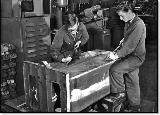
Apprentice Brian Marsh (RHS) hand scraping the surface for flatness. Dalmuir 1955
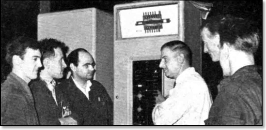
Electricians training on how to maintain the Control Panel
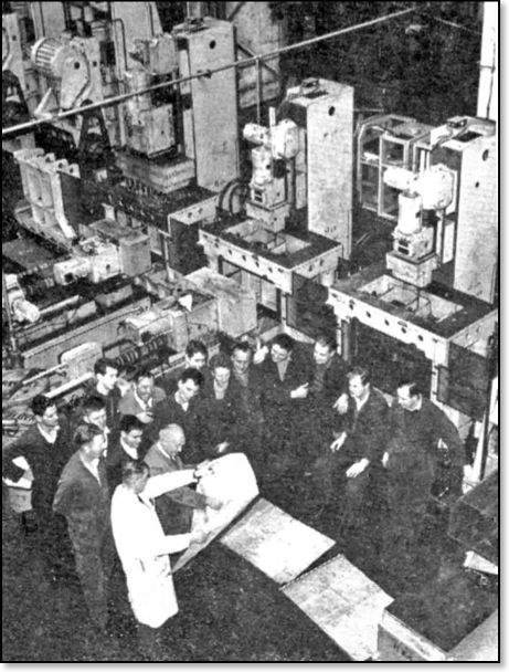
Team Meeting
_____________
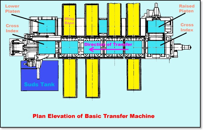
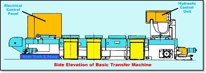
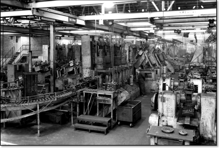
Both views shown without the Unit Heads
Points of Interest Regarding Transfer Machines
Multiple Indexing
On every machining line there are always one or two operations which take longer to perform than the rest. For various technical reasons it is not always possible to break these down into smaller time factors or steps, and so, on a transfer machine, the cycle time is governed by these particular operations. We have found a method of overcoming this difficulty by duplicating the stations with the longest times and providing a compound indexing system which enables the overall machine to be run as a unit, and which by shortening the time cycle, allows a transfer machine to produce more by the addition of a few stations instead of duplicating the whole machine. Another point is that it is a fairly simple matter to rotate the component through 90 deg. both in the vertical or horizontal planes in order to work on other faces of the component. The governing factor will be how much of the fixture is left after allowing for all cutter clearances.
Apart from the technical side there are other points arising from the use of transfer machines. Firstly, it is extremely difficult for operators from stock-piling work between machines, owing to tool changes, personal reasons, breakdowns and discrepancies in floor to floor times of adjacent machines. The floor space so occupied represents production space, rent, buildings, lighting, heating, etc., whilst the stock also represents idle capital. The ideal condition is to have the smallest quantity possible in the manufacturing pipeline, that is, of course, one component per machine. The transfer machine goes quite a long way towards meeting this ideal, admittedly it sometimes breaks down, or has to be stopped for tool changes, but there is no out of balance of stock created between the beginning and end of the machine, only strategic stock being required between the transfer machine and the next machine.
The question of consistent quality production from a transfer machine requires an entirely new approach. The present method where an operator is loading and unloading a group of individual machines has led to the habit of the patrol inspector, using the operator as an auxiliary inspector. The transfer machine, of course, does not allow this because as far as the operator is concerned, what happens between him and the other end is out of his control. To safeguard this position, it is necessary to put in gauging and clearing stations, which, by use of the latest Sigma type of gauge, can stop the machine should out of size tolerances be detected.
Shop Organisation
It is essential that an efficient shop organisation should be built to back up transfer machines if the best is to be got out of them. In this connection three points stand out. Firstly, if the machine is to produce accurately and consistently components, tools must be kept up to a good standard. It is necessary, during the trial and pilot runs, to carry out an analysis of the life of all the tools on the machine between regrinds, and also the total life. From this can be determined the maximum interval which can be allowed between tool changes. It is a good policy to stop the machine at definite times in the day and change certain tools before proceeding with the next run. Tool changing can be assisted, to a great extent by the use of setting gauges. For instance, we provide a drill setting gauge for each multi-head so that the new drills can be set to the correct length in their adjustable holders before insertion to the multi-head. In the same way boring and other tools can be pre-set before fastening in the machine. To help this we also provide tool cabinets for each machine, which contain a complete set of tools and setting gauges for each station.
The second point concerns inspection. As mentioned before, we can fit automatic gauges at vital points on the machine, but this is not enough in itself. There must also be a check by means of a patrol inspector who will test occasional samples to see that deterioration is kept under control.
The third point is maintenance. In order to keep production at full blast, a team of men must be trained who know the machines well and they must be backed by an ample supply of spares. Should a unit head break down it should be possible to whip off the defective unit complete and substitute a new one in a short period. As so much depends on the electrical switches, relays and interlocks, the electrician is obviously a key man in this team, and will become more important as development proceeds. Of course, the question of maintenance is simplified by the standardisation of the various machine parts.
_____________
THE DESIGN OF TRANSFER MACHINES
Presented by H. W. Holbeche
In going on to a description of the design of transfer machines, it must be emphasised that there is no one solution to the problem, and to describe all the variations in design would be beyond the scope of this paper. The aim, therefore, has been to give a technical description of the B.M.C. machines and the reason for the adoption of specific designs.
Three Main Types
There are three main types of transfer machines, the straight line type, the rotary indexing, and the horizontal drum type machine. In order to obtain any of these machines in a reasonable time it is essential to standardise the various constituent parts, and the first necessity is to have a range of unit heads which can drive the tools and supply the necessary fast and slow traverse motions to those tools.
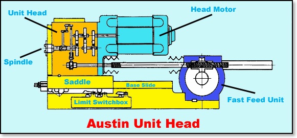
There are various types of unit heads, and the method of traversing may be hydraulic, cam operated, hydro-pneumatic, or mechanically by lead-screw. In the search for a completely universal unit head it was decided to adopt the screw feed principle in preference to the hydraulic principle, partly because this type of head is the only one which can be used satisfactorily for tapping, in addition to the usual drilling, boring, reaming, etc.
Austin Unit Heads
Five sizes of unit heads were designed, all having the same basic design, ranging from the small No. 0 Unit, suitable for small drills and high spindle speeds up to the No. 3 size for heavy work involving drill pressures up to 10,000 lbs.
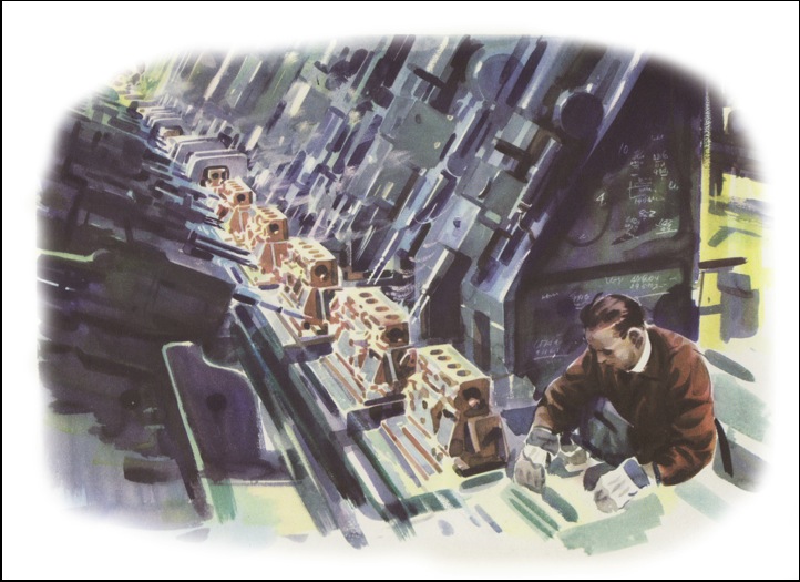
Drilling ‘B’series cranks in No 5 machine shop
STRAIGHT LINE TRANSFER MACHINE
There is a difference of opinions as to whether platens should be used for carrying the work, or whether non-platen machines are preferable. In the case of the platen type machine, a fixture is attached to each platen. The component is loaded in this fixture and the component fixture and platen are indexed from station to station along the length of the machine. The platen has to be accurately located and clamped at every station, and unless this location is extremely accurate, it will be realised that work done at one station may not be relative to the work done at a previous station.
In the non-platen type of machine there is a clamping and locating fixture permanently fixed at each station; the component is transferred from station to station, located and clamped. An advantage of this method is that there are no platens to return to the loading end. Another advantage is that the pilot bushes for the tools or pressure plate are incorporated in the fixture or bracket which carries the component locations, thus giving greater accuracy. This system is most suited for handling components such as cylinder blocks and cylinder heads, and some types of gearboxes; in fact any job which has a suitable face or faces to locate from. It is, however, almost impossible, or at any rate very difficult to machine such components as exhaust and inlet manifolds, connecting rods, axle cases, valve rockers, etc., on a non platen machine.
As one of the desired features of the proposed machines was that they should be constructed from standard sections carried in stock and be capable of application to any type of component likely to be required, the platen type of machine was decided upon. Subsequent experience and the quest for completely automatic machines requiring no operators have shown that there is a need for both types. On investigation it was found that the design of the transfer bed for the platen type of machine could also be used without alteration for the non platen type.
Platen type machines can be run by one or two operators depending on the relative machining and loading times. If the loading and unloading times together are less than the machining time, then the machine can be run by one operator provided that the platen with its fixture and component can be returned automatically to the loading station.
Machine Construction
The backbone of the machine is to built up from a number of centre beds, each bed having either two or three stations, together with a loading station at one end and an unloading station at the other. The machine is completed by attaching to the centre beds the necessary branch beds on which are mounted the unit heads, columns, etc.
Platens
The work holding fixtures are mounted on standard platens. These platens are grooved at the sides and slide along the machine on keep plates bolted to the machine beds. The platens are transferred from station to station by a transfer bar pulled by a hydraulic cylinder, the standard distance of transfer being three feet. To the transfer bar are attached small blocks, which engage hinged pawls projecting from the underside of the platen, along with bushed location holes for positioning the platen accurately at the stations. The transfer bar positions the platens only approximately, vertical plungers operated by hydraulic cylinders through toggles, locate the platen accurately, and clamp it upwards against the keep plates. There are four clamping plungers at each station, two of which also act as locators for the platen. It will be noticed that it is the underside of the keep plate which forms the vertical location, so that wear on the plate or the platen caused by sliding action does not affect the accuracy of the location. This feature is the subject of a patent taken out by Messrs. James Archdale & Co. Ltd.
Transfer Machine in East Works for ‘A’ series blocks
_____________
It must be remembered that Austin were among the pioneers of the automatic transfer system, which aims at combining in one machine, operations usually performed by a series of separate machines with separate operators.
Having a transfer line has many cost advantages. A typical transfer machine producing cylinder blocks for A.40 engines, which has replaced a line of 13 other machines. Is now producing 3,000 blocks a week compared with 2,500 turned out by the standard machinery. It cost a total of £25,903 against £30,850 for the standard machines. Yet it has cut operating costs from £4 8s 9d. an hour to £3 13s. 3d. and labour costs from £2 17s. 2d. to 11s an hour. The total saving in addition to higher output is £123 per 40 hour week. This particular line needed 110 square feet of floor space less than the system it replaced.
Only two operators are required on the transfer machine one loading and one unloading. And the progress of every component through the 13 different processes is traced and checked on control panels which are a blaze of red and green lights. To speed the supply of transfer machines, Austin's have built their own machine tool department. More impressive plant is also being designed, one machine can now take the place of 25 others.
Austin's have helped to produce for BMC, three transfer machines which carry out all but 20 of 100 major processes in manufacturing a cylinder block. The machines are controlled by an electronic " brain " and turn out a virtually finished block every 3.25 minutes.
Mr F Griffiths Austin's chief production development engineer, has given this forecast of the future: "The transfer machine will take in the raw material at one end cast it or forge it, machine it and deliver the finished component either to the assembly point or ready painted and packed for despatch.