

Car Assemble Building 2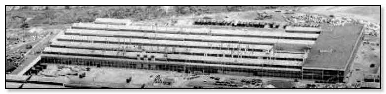
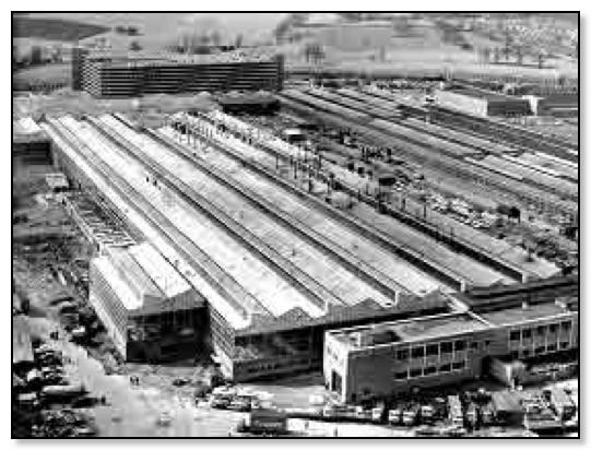
Aerial View 1965
How they planned for this new assembly facility
The new car assembly building, CAB 2, constructed at Longbridge in the early 1960s, was the biggest single contribution to BMC's £49 million expansion plan to increase production from 750,000 to 1 million vehicles a year.
CAB 2 was basically similar to CAB 1 except for one unique feature; the double storey South end was designed for body storage. The new building occupied space formerly used for parking vehicles awaiting dispatch; these vehicles were subsequently accommodated in the new £550,000 multi-storey car-park.
Compared with CAB 1 working conditions were ideal; with various improvements included a wax supply house, and wax-mixing facilities, with circulating lines for quick application. Cars for export, are were waxed, to ensure that overseas dealers received them in showroom condition.
There was automatic mixing and feed of anti-freeze for winter use, and car paint rectification in a much more advanced lay-out. Cars were moved on a conveyor through the spraying area to the ovens, and then to the cooling area, etc.
Initial planning for CAB 2 started in August 1959. Costing £3.3m, this glass-sided building was 960 ft long, 360 ft. wide, and could paint, trim, and final assemble 2,500 vehicles a week. It was the first self-contained unit at Longbridge able to carry out all three phases of production under one roof.
It was very difficult to visualise how the assembly lines would look from a drawing, so a team of model makers, Trevor Shortland, Bob Sharp and Fred Watkins, worked in the strange world of miniaturisation, producing a 1/32 scale model. Here fork lift trucks were three inches high and a finger touch could overturn a Mini, or send a stack of bins crashing in Lilliputian chaos. The model had to be perfect in every detail, having cars, forklift trucks, pallets and all the overhead conveyors. From various wooden patterns, the works foundry cast items needed in the quantities required.
Projects of this nature required discussion of various points with supervisors and management. Showing them the 3D model simplified the task, highlighting potential problems, for example, the difference in levels between the floor and ground level. On drawings it was hard to understand what a headache this would be, but the scale model clearly showed the need for a gently sloping access road to CAB 2. Former Longbridge employees know that the only flat ground was East Works and the New West Works. Although making this model took about 2,500 hrs, flagging up problems before construction proved well worth while.
When model-makers were not putting up roof supports, or stacking bins and pallets, they were generally in the Planning Department at their drawing-boards; making these delightful yet thoroughly practical models was only part of their work.
Model Makers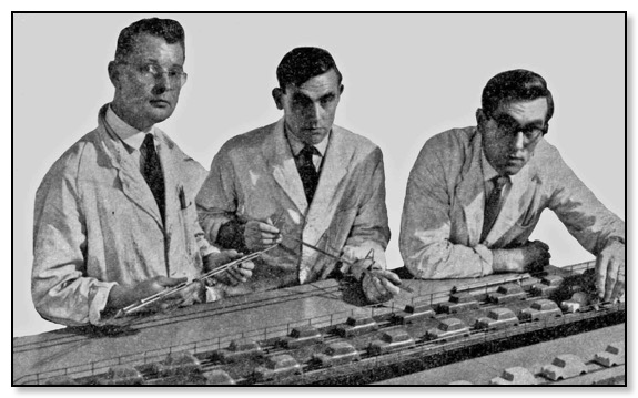
Trevor Shortland xxxxx Bob Sharp xxxxx Fred Watkins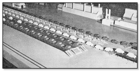
Model showing the trim and assembly tracks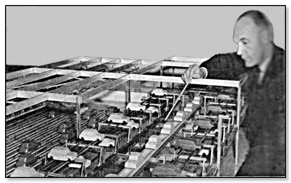
Model of the Body Store
Above shows the automatic body storage system which Mr. Cross is explaining on the model. He is pointing out the work-in-progress track; the double-tiered tracks on either side of the storage tracks for bodies before painting. The lower tracks on the left are for bodies after final paint.
Building Work Starts
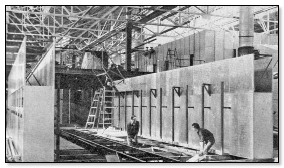
The first requirement was to level the site and pile drive over 1,100 piles deep into the ground. For the foundations, 23,000 cubic yards of concrete were needed. Early in November 1961 work started on the steelwork, all 2,500 tons, covered with over 5,000 sheets. With the external building finished, work began on plant installation, such as excavation for the new paint plant’s underground settling tank and filtration plant, 120ft long, 60 ft wide, and 15 ft deep, with a capacity of 120,000 gallons.
CAB 2 was a joy to work in as the planners incorporated new ideas. It was a light and airy building having 108,200 sq. ft. of glass in its construction. It was efficient as items were in the right place at the right time thanks to a complex modern conveyor system.
Installing the paint facilities
Fire precautions were most carefully planned and the building was fireproof. If a fire started outside there would be ample time for fire services to control it before it ate its way into the new building. Wherever paint is handled there is always a fire hazard, and the latest fire protection and fire prevention measures were incorporated into the design of the Paint Plant section of CAB 2. Sprinklers were installed but a double safeguard was incorporated, a one-foot-thick steel and asbestos fire-wall dividing the Paint Plant from other parts of the building. The wall was estimated to give a margin of four hours' resistance to fire should an outbreak occur on either side, giving ample time, for the outbreak to be controlled by the available weight of fire-fighting force. Doors in this wall were equipped with 'fusible links' which melted at certain temperatures, closing the doors, thus effectively sealing off any outbreak.
CAB 2 had a new installation, a storm-test vestibule, the most advanced in the motor industry at the time. It provided a 40 mph gale at the touch of a button, and water could be directed onto a car at a pressure of 180 lb/sq.in., searching out leaks which could annoy motorists driving long distances in English weather! Precise control over the storm-test enabled operators to pin-point pressurized water and strong blasts of air to any part of the vehicle, even to previously inaccessible parts underneath the car. All this could be done while the car operated under road conditions, for the new rig had rollers which enabled the car to run in gear, giving true road conditions in every respect.
Steam supply to CAB 2
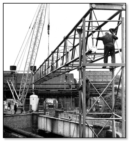
Installing the bridge over the railway to carry the steam pipes
It was necessary to supply steam in sufficient quantity, estimated at 60,000 lb an hour, and at sufficient pressure to keep the CAB 2 Paint Plant spray booth air-conditioning apparatus running, hot water flowing from taps, and radiators warming the building in winter; in fact, steam the amount of used in two hours would keep an average small family house heated for a winter.
The nearest source of steam was the boiler-house in North Works, half a mile away. To bring steam from there to CAB 2 entailed laying the longest steam main at Longbridge, and the building of a single-span bridge over the railway line near the boiler house, at a cost of over £50,000. Much of the laying of the steam main was done with little difficulty or inconvenience to production or internal communication, except for finally placing the bridge, accomplished over the weekend 15-16 July 1962.
Except for a bridge-lifting operation, taking only 30 minutes, the months of planning ensured that everything went smoothly. The bridge was assembled in sections, and a 60ft. jib-crane hoisted the 135ft span, weighing 8.5tons, into place over the railway, a mammoth jig-saw puzzle successfully solved by the works engineers.
Supplying increased steam needed two new oil-fired boilers to be installed in the North Boiler House. If it became necessary to lay other pipes from the boiler-house because of future expansion, a ready-made route now existed. To allow for expansion of the pipes the new steam main had sliding expansion joints. If you could imagine this huge length of pipe laid in a straight line, and filled with scalding steam it would expand by over 12ft.
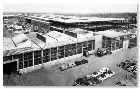
CAB 2 nearing completion, view from the multi-storey car park
Experience gained in CAB 1 was always taken into account in designing CAB 2; this was particularly evident with the Control Room which is, in effect, hung from the roof, giving an unrestricted view of the entire working area. The Production and Conveyor Controller were 14 ft. above floor-level, enabling them to see all that went on and deal instantly with any hold-up. Their modern push-button control kept completely in touch by a mimic diagram 12 ft. long and 10 ft. high, with a rippling light system showing the conveyors actually at work etc.
Major sub-assemblies and body panels from Fisher & Ludlow were delivered to West Works, where they were welded up into complete primed body shells. These were then transported by trailer to the CAB 2, picked up by automatic hoists, placed on storage conveyors and then onto the work-in-progress conveyor. At the other end they were lowered to the Paint Shop and, after painting, were returned to the storage balcony. The next operation took them to the Body Finishing tracks for interior trim. As bodies were reaching the end of the body finishing lines their respective engines, sub-frames, and suspension units were being assembled to await the trimmed body, all this to a pre-determined sequence as they met at the start of the car assembly lines.
Coming off these lines, each completed, car then went on to inspection, static roller testing, and storm testing, with rectification bays at hand if needed. Finally came the last clean and polish on the car finishing line before the car finally went for dispatch.
North end of CAB 2
When the building was fully operational it employed 1,079 men and 41 women working on the actual production lines. A further 485 men and 17 women were employed on ancillary work. Working conditions were improved compared to CAB 1, in that everyone in CAB 2 had an individual locker in a locker room, and those who had tools to leave behind at the end of the shift safely left them in a locked tool cabinets.
An innovation at Longbridge was conveniently placed tea and coffee vending machines, made within BMC by the Vending Machine Division of Fisher & Ludlow's; these had been a big attraction at a British Trade Fair in Moscow.
Offices in CAB 2 included those for the superintendent, foremen, production controllers, time-keepers, and rate fixers. To look after employees’ welfare there was a large Ambulance Station fully equipped to cope with all minor injuries. If further medical treatment was needed the employee would be transported to the Health Centre or local hospital.
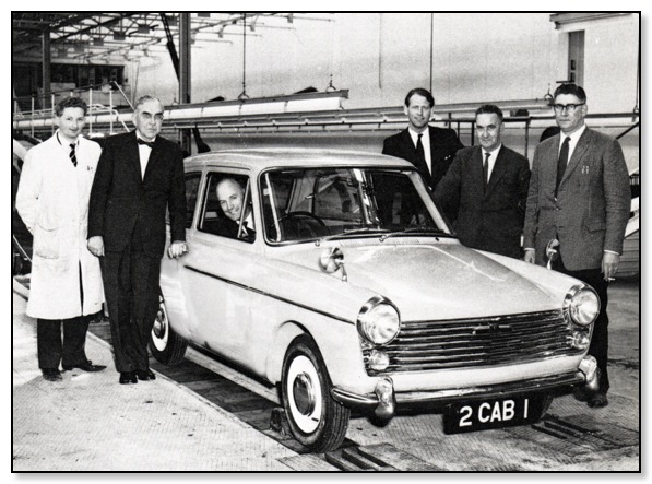
First A40 MKII CAB 2 November 1962
You may be surprised to see from the above picture that the first car to be produced on Track 1 was the new A40 MKII. The A40 MKI had been produced formerly in CAB 1. By transferring production to CAB 2, CAB 1 could increase production of the Mini.
When Track 2 came on stream it first produced the Morris 1100 for about six months. Then production changed over to making the Austin version ready for the launch on 6 September 1963. By that time CAB 2 was producing 2,500 cars a week, bringing total production at Longbridge to 10,500 vehicles a week. With demand for the A40 MKII decreasing, production was switched back to CAB 1, but onto a different track from that used before. Therefore CAB 2 was only producing the Austin version, but later on this included the Vanden Plas, Riley, Wolesley and MG.
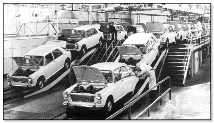
CAB 2 with both tracks producing the Austin 1100